

Flexible printed circuits (FPCs) and rigid-flex PCBs are two types of flexible circuit boards that allow bending and flexing in electronic devices. However, there are some key differences between FPC and rigid-flex technology:
FPC Construction
FPCs consist of conductive copper traces etched on a thin, flexible dielectric base layer such as polyimide. The polyimide substrate only has copper on one side.
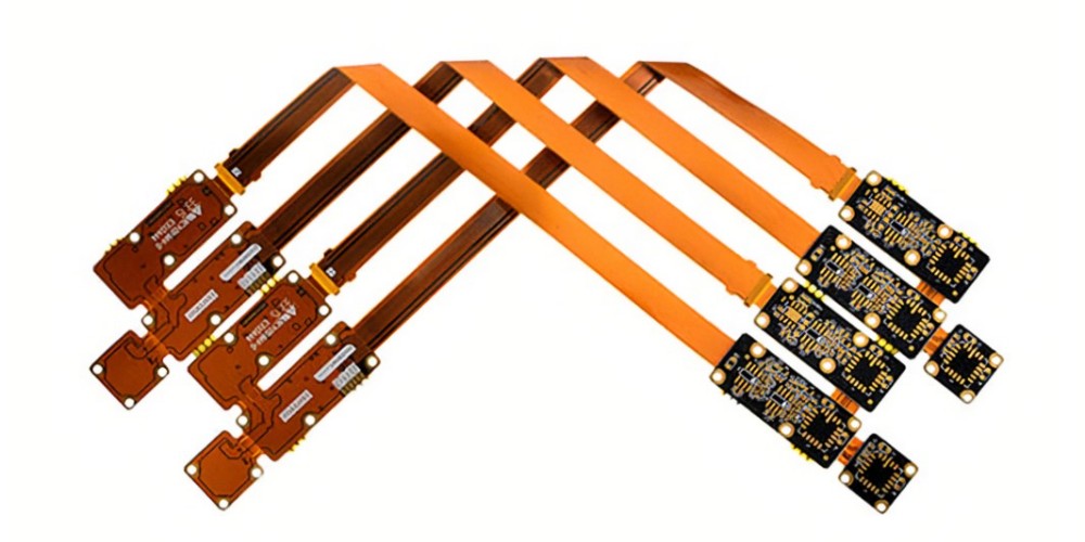
FPCs use an adhesive layer to attach the flex circuit directly to the surface of a rigid printed circuit board (PCB). The components are mounted on the rigid PCB surface.
FPC Substrate Materials
- Polyimide films like Kapton or Upilex are commonly used.
- Polyester films like PET are lower cost but have lower temperature resistance.
- Thickness ranges from 25μm to 75μm typically.
Coverlay
FPCs use a coverlay layer to protect the copper traces. Polyimide provides the best protection. Liquid photoimageable coverlays are also used for improved adhesion and processing.
Bonding Adhesive
FPCs use acrylic, epoxy, or thermoplastic adhesives to bond to the rigid PCB substrate. Anisotropic conductive films (ACF) are commonly used adhesives for display and IC bonding.
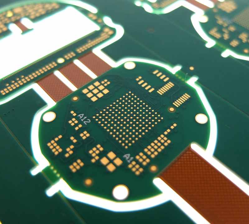
Rigid-Flex Construction
Rigid-flex PCBs integrate flexible circuits and rigid boards into a single structure. The flex layers are laminated between rigid circuit board layers.
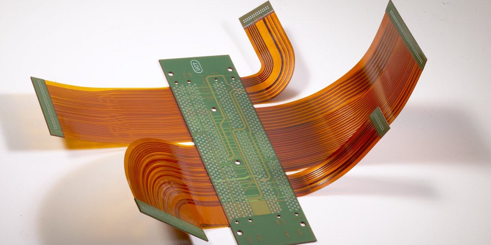
Components can be mounted on both the rigid and flex areas of the circuit. The rigid regions provide mechanical support while the flex areas allow dynamic movement and electrical connections.
Flex Dielectric Material
Polyimide is most commonly used but polyethylene terephthalate (PET) and polyester are also options for the flexible layers.
Copper Thickness
1/1 oz copper up to 2 oz copper on the flex layers. Rigid layers can use thicker copper.
Coverlay
Liquid photoimageable (LPI) coverlay provides the best reliability for rigid-flex boards. It can bend without cracking.
Bonding Films
Acrylic or epoxy adhesives are used to bond the rigid and flex layers together during lamination.
Manufacturing Process Differences
FPC Fabrication
FPC production consists of the following general steps:
- Copper foil application – Copper foil is laminated onto the polyimide base substrate
- Photolithography – The copper traces are imaged using photoresists and etching
- Coverlay application – The protective coverlay layer is added
- Laser cutting – The individual FPC circuits are cut from the panel
FPCs leverage the roll-to-roll processing used in the flexible packaging industry. Reels of polyimide and coverlay are processed through feed-through systems for imaging, laminating, and testing.
Rigid PCB equipment is not used. FPC production utilizes lower-cost, reel-to-reel processing.
Rigid-Flex Fabrication
Rigid-flex PCB fabrication involves both rigid PCB and flex circuit processes:
- Rigid layers – Individual rigid circuit layers are fabricated first using standard PCB processing (imaging, plating, etching).
- Flex layers – The flexible layers are etched and covered similar to FPCs.
- Lamination – The flex and rigid layers are bonded together using adhesive films.
- Drilling – Holes are drilled through the entire rigid-flex stackup.
- Plating – Metallization is deposited onto the hole walls.
- Finishing – Solder mask, silkscreen, edge connections are completed.
Rigid-flex fabrication requires both rigid PCB and flex circuit manufacturing capabilities. The specialized laminating and drilling equipment adds cost and complexity compared to pure FPCs.
Performance Differences
Flexibility
FPCs can have very tight bend radii, often below 3 mm. Rigid-flex boards are limited to bend radii of 6 mm or greater to avoid damaging the rigid layers.
FPCs have higher flexibility for dynamic folding applications. Rigid-flex provides moderate flex capabilities combined with rigid support.
Layer Count
FPCs are typically single or double layer. Rigid-flex boards can integrate multiple flex layers and high layer count rigid sections.
Component Mounting
For FPCs, components are mounted on the rigid PCB and contact pads on the flex circuit traces. Rigid-flex allows components to be mounted directly on both rigid and flex areas of the circuit.
Reliability
The integration of multiple lamination steps and different materials makes rigid-flex PCBs more prone to interconnection failures and cracks during dynamic flexing.
FPCs laminated onto a single rigid substrate have less risk of delamination or cracking during bending motions.
Design Complexity
Rigid-flex PCBs enable more complex circuit and component layouts across both rigid and flex regions. FPCs have simpler 1-2 layer construction but can achieve very tight folds and bends.
Cost
FPCs leverage lower cost reel-to-reel processing without rigid PCB equipment investments. Rigid-flex has higher costs due to the combination of both rigid PCB and flex circuit fabrication processes.
Summary Comparison
| Parameter | FPC | Rigid-Flex PCB |
|---|---|---|
| Construction | Flex circuit adhesive bonded to rigid PCB | Multilayer integration of flex circuits and rigid board sections |
| Flex Dielectric | Polyimide, polyester | Polyimide typically |
| Manufacturing Process | Reel-to-reel processing | Combination of rigid PCB and flex fabrication |
| Bend radius | Below 3 mm typical | 6 mm minimum |
| Layer count | 1-2 layers | Multiple flex + rigid layers |
| Component mounting | On rigid PCB only | Both rigid and flex regions |
| Reliability | Less prone to cracking and delamination | Higher risk of interconnect failure during dynamic flexing |
| Design complexity | Simpler construction | Enables complex rigid-flex layouts |
| Cost | Lower cost reel-to-reel processing | Higher cost due to rigid PCB and flex circuit production |
Applications
FPC Applications
FPCs are ideal for:
- Tight bending applications like wearables and foldable displays
- Low complexity circuits with minimal layer counts
- Cost-driven designs where lower price is critical
Common applications:
- Wearable devices
- Mobile phone flex cables
- Automotive flex circuits
- Display connections
- Printer flex cables
Rigid-Flex Applications
Rigid-flex PCBs are preferred for:
- Dynamic flex connections combined with rigid mounting regions
- Complex circuitry with high layer counts
- Mission-critical electronics where robustness is necessary
Common applications:
- Military systems
- Aerospace electronics
- Medical instruments
- Industrial equipment
Frequently Asked Questions
Can components be mounted directly on FPCs?
Most FPCs do not allow direct component assembly. Components are mounted on the rigid PCB and the FPC is used for interconnections. However, some FPC assemblies called “flexible printed electronics” allow simple components to be mounted directly on the flex circuit traces.
What are some key rigid-flex PCB design guidelines?
- Place high-performance components on the rigid portions while interconnects go on the flex areas.
- Maximize commonality of layer stacks between rigid and flex sections.
- Avoid sharp flex bends next to a rigid-flex joint. Use rounded bends.
- Spread plated through holes across both rigid and flex areas to avoid stress points.
Can FPCs substitute for rigid-flex in some applications?
In some less complex, cost-driven designs, FPCs can potentially replace rigid-flex. Especially if the flex circuit just needs to interconnect a few sections of a simple rigid PCB. However, rigid-flex PCBs enable much more robust and complex board-level integration of flexible and rigid sections.
What are some key benefits of FPCs versus rigid-flex?
FPC advantages include:
- Extremely tight bend radii below 3 mm
- Lower costs due to reel-to-reel processing
- Simpler single or double layer construction
- Potentially faster fabrication time
What are some disadvantages of FPC technology?
FPC limitations:
- Components cannot be mounted directly on the flex circuit
- Less robust mechanical integration with the rigid PCB
- Susceptible to tear-out failures at the FPC-board interface
- Limited in design complexity due to 1-2 layer construction