Compact instruments
Define cleaning, traceability, and the device-specific reliability plan.

Fewer interconnects. More design freedom.
Connect your design decisions to a buildable board. Explore rigid-flex stackups, check the geometry, and prepare a clear specification for your next project.
Practical engineering resources. Project-specific manufacturing review.
01 / The construction
A rigid flex PCB combines rigid circuit-board sections with flexible copper circuitry in a single integrated assembly. The rigid regions support components, while polyimide-based flex regions connect them across folds or moving interfaces. This construction can replace separate boards, cables, and connectors when packaging, connection reliability, or assembly space drives the design.
Think in regions rather than a single board thickness. The rigid sections, exposed flex, and transition each have different mechanical and electrical constraints. A successful design starts with the enclosure, assembly sequence, and movement requirement, then develops a stackup that supports them.
Use the rigid-flex design guidelines to translate those constraints into a drawing. If the main objective is only to reinforce a connector tail, compare rigid-flex with a flex circuit and stiffener before adding manufacturing complexity.
| Parameter | Define before layout |
|---|---|
| Copper layers | Total in each rigid region; layers continuing into flex |
| Thickness | Finished rigid and flex thickness separately |
| Bending | Installation or repeated motion; radius and direction |
| Electrical | Impedance, current, return path, and test requirements |
| Materials | Laminate, foil, coverlay, adhesive, and bonding system |
02 / Engineering workbench
Explore the tradeoffs before releasing a fabrication package. These tools run in your browser and carry your selections into the quote form. Results are planning inputs; they do not certify compliance, predict fatigue life, or confirm a supplier’s capability.
Screen the finished flex construction. Published guidance is not a qualified minimum bend radius.
Enter your requirements to begin. JavaScript is required for calculations.
Map layer continuity across rigid and flex regions. This conceptual drawing is not a fabrication stackup.
Enter your requirements to begin. JavaScript is required for calculations.
Build a material discussion list from your operating requirements.
Enter your requirements to begin. JavaScript is required for calculations.
Ballpark estimate, not a quotation. Dollar ranges require a calibrated manufacturing model.
Enter your requirements to begin. JavaScript is required for calculations.
Need more context? Read the dedicated bend radius calculator guide, stackup builder notes, material selection guide, or cost estimator assumptions.
03 / Stackups & types
A four-, six-, or eight-layer rigid-flex board usually describes the copper count through a rigid region. The flexible interconnect may carry fewer of those same layers. Do not add the flex layers again when reporting the total. Show which copper layers continue across each region and where every dielectric, coverlay, and bonding layer ends.
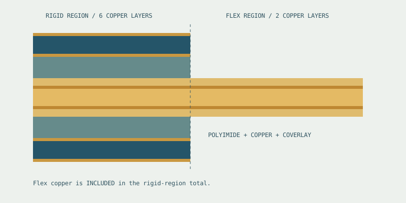
| Construction | Useful design question |
|---|---|
| 4 / 6 / 8 layer | Can routing and return paths fit with fewer flex layers? |
| HDI rigid-flex | Do component escape requirements justify microvias and sequential lamination? |
| Bookbinder | Do different flex sublayers need different lengths through the bend? |
| Air gap | Must selected flex sublayers remain unbonded to allow relative movement? |
Bookbinder and air-gap constructions need deliberate mechanical drawings, not just a checkbox in a quotation. Layer separation, free length, bend order, and termination details affect assembly. Start with the regional stackup guide and use the HDI construction guide when fine-pitch escape routing changes the build sequence.
04 / Materials
The copper, flexible dielectric, coverlay adhesive, and rigid bonding materials must work together through fabrication, assembly, and service. A high glass-transition temperature alone does not define the allowable operating temperature of a finished board. Use supplier datasheets and a qualified process for the complete construction.
| Material decision | Engineering role | Review point |
|---|---|---|
| Polyimide flex core | Flexible electrical insulation | Thickness, moisture behavior, thermal and electrical data |
| Adhesiveless vs adhesive-based | Changes the flex composite | Finished thickness, bonding interfaces, process compatibility |
| RA vs ED copper | Conductor material and mechanical behavior | Grade, elongation, thickness, grain, and bending duty |
| Coverlay | Insulates and protects exposed flex copper | Adhesive thickness, pad openings, registration |
| No-flow / controlled-flow prepreg | Bonds the rigid regions | Resin movement around flex windows and edges |
| Stiffener | Supports a local contact or component area | Edge location, adhesive, support, and strain relief |
Rolled annealed copper is commonly considered for repeated bending, but the name alone does not establish cycle life. Likewise, a halogen-free laminate does not prove the full board is halogen-free. Ask for documentation covering every relevant material. Compare the options in the rigid-flex materials guide.
05 / Cost planning
Fabrication price depends on more than area. Flex layer count, sequential lamination, coverlay processing, panel utilization, test coverage, and production quantity all affect the work required. Expedite requests can also constrain material and production choices. A small board with a difficult construction may cost more than a larger, simpler one.
Compare installed cost against separate rigid boards, connectors, cables, assembly operations, and system test. Keep the mechanical envelope and electrical requirements constant when comparing quotations. Otherwise, a cheaper alternative may be a different product rather than a better price.
Reduce avoidable cost by simplifying the flex substack, using compatible stocked materials, reviewing the outline for panel use, and stabilizing the fabrication package before release. Ask which tolerance actually drives cost instead of relaxing every tolerance.
See the cost drivers and RFQ comparison guide and cost planning tool. For another view of orderable constructions, explore custom rigid flex circuit boards and compare the proposed stack, testing, and delivery assumptions.
06 / Design quick reference
| Design area | Practical starting point |
|---|---|
| Bend radius | Calculate from finished flex thickness using a documented construction-specific rule; qualify repeated motion. |
| Transition zone | Agree a component, via, and feature keep-out with the fabricator; define the rigid edge on the drawing. |
| Routing | Use smooth direction changes, review trace orientation, and avoid abrupt width changes inside the bend. |
| Vias and pads | Keep stress-sensitive plated features away from bending; agree any exception explicitly. |
| Reference planes | Balance signal return requirements against flex thickness and stiffness; do not hatch planes without electrical review. |
| Assembly | Check the folding order, fixture support, service loop, and component clearance in the final enclosure. |
Treat IPC-2223 as a design-standard reference and IPC-6013 as a performance-specification reference. Identify the applicable revision, class, and project requirements in the purchase documentation. A general online ratio or drawing does not demonstrate compliance. Review the detailed design checklist before freezing the stackup.
07 / Applications
The same rigid-flex layout approach does not fit every application. The operating environment, expected movement, inspection plan, and field replacement strategy set the requirements. Industry labels below describe design considerations; they are not claims of certification or approved supplier status.
Define cleaning, traceability, and the device-specific reliability plan.
Review environment, traceability, and qualification requirements early.
Specify temperature exposure, vibration, and the product validation plan.
Plan the fold, skin-adjacent environment, and battery or connector loads.
Distinguish installation flex from continual movement in machinery.
Compare assembly effort, packaging, and serviceability across volume.
Browse all rigid-flex applications, including camera modules and drone electronics.
08 / Fabrication & verification
A capability table is only useful when it applies to the actual construction. Send the stackup, rigid-to-flex boundary, smallest features, impedance requirements, and inspection needs together. RigidFlexPCB coordinates inquiries with manufacturing partners; partner limits, certifications, and delivery commitments are confirmed per project.
| Capability to confirm | Evidence to request |
|---|---|
| Layer structure and materials | Reviewed regional stackup and exact material system |
| Trace, space, and drilled features | DFM response covering copper weight, layer type, and tolerances |
| Controlled impedance | Approved geometry, coupon construction, target, and tolerance |
| Electrical and mechanical quality | Test method, acceptance criteria, documentation, and sampling |
| Prototype and assembly schedule | Material availability, tooling, fixture needs, and agreed release date |
Use the capability review checklist, then compare the manufacturing process, prototype plan, and assembly requirements. A review of rigid-flex PCB fabrication services can help frame supplier questions, but verify each claimed limit against your proposed build.
09 / Architecture tradeoffs
| Approach | Where it helps | Tradeoff to review |
|---|---|---|
| Integrated rigid-flex | Constrained three-dimensional packaging; fewer separable connections | Construction cost, supplier dependence, whole-assembly replacement |
| Flex with stiffeners | A flexible interconnect with localized support | Stiffener support is not a multilayer rigid interconnect region |
| Rigid boards + cable / connectors | Modularity and field replacement | Connector volume, mating operations, routing and cable management |
| Semi-flex | Limited installation forming with a suitable construction | Material and bending limits differ from polyimide-based rigid-flex |
Choose the architecture that meets the system requirement with an acceptable build and service plan. Count assembly operations, connector retention, enclosure constraints, and repair access alongside bare-board cost. The construction comparison guide walks through these decisions.
10 / Common engineering questions
A rigid-flex board integrates structural rigid sections and flexible interconnects into one manufactured circuit. A flex PCB may have local stiffeners, but a bonded stiffener does not create the same plated multilayer rigid region. Compare component support, interconnect routing, assembly, and replacement requirements before choosing.
Usually, yes: a six-layer rigid region with a two-layer flex section contains six copper layers in that rigid region, two of which continue through the flexible span. Always confirm the regional stackup drawing because shorthand such as “6+2” can describe different constructions.
It can be designed for repeated movement, but that capability is not automatic. Flex thickness, copper grade, layer count, bend geometry, travel, environment, and strain relief affect performance. Specify the duty cycle and qualify a representative assembly instead of inferring life from a bend-radius ratio alone.
Start with the finished flex composite thickness and a documented rule for the actual construction and bending duty. Published reference multipliers differ. The calculator labels its source and limitations; the final drawing needs a fabricator-approved radius and a test requirement where repeated bending matters.
Specialty laminates, multiple lamination steps, coverlay registration, handling, testing, and panel utilization add work. The useful comparison is the installed system: the board, connectors, cables, assembly labor, test, and expected yield. A higher bare-board price may still fit a lower total system cost.
Yes, with a defined reference path and a regional stackup designed for the required impedance. Rigid and flex dielectrics, coverlay, copper geometry, and transitions differ. Agree the target, tolerance, frequency range, and coupon strategy with the fabricator before freezing trace widths.
RigidFlexPCB is an engineering resource and inquiry site. Project quotations and production are coordinated with manufacturing partners. Factory capabilities, certifications, delivery commitments, and inspection requirements must be confirmed for the partner and construction proposed for your project.
Provide fabrication data, a dimensioned outline, a regional stackup, rigid-to-flex boundaries, bend locations, quantities, material requirements, and the requested delivery schedule. Include a BOM and placement data when assembly is required. Mark anything provisional so the quotation does not assume it is final.
Yes. Define what the prototype must prove: fit, electrical continuity, impedance, assembly, or bend endurance. Use representative materials and geometry when qualifying construction. A prototype built with a substituted stack cannot by itself qualify the intended production stack.
No. They help organize early choices and make assumptions visible. The stackup is conceptual, material suggestions are a discussion list, and a price range needs a calibrated model. Send the tool parameters with your files for a project-specific review.
11 / Your next build
Share the information you have, even if the design is still evolving. State which dimensions and materials are fixed and which need review. For assembly, include the bill of materials and placement data. For repeated motion, describe travel, frequency, bend direction, and the qualification target.
The RFQ file checklist helps organize a complete request. You can also read engineering notes or learn how this resource and its manufacturing partners work. Send confidential project information only when you are authorized to share it. Quote scope, schedule, and production requirements are agreed after review.