

Introduction
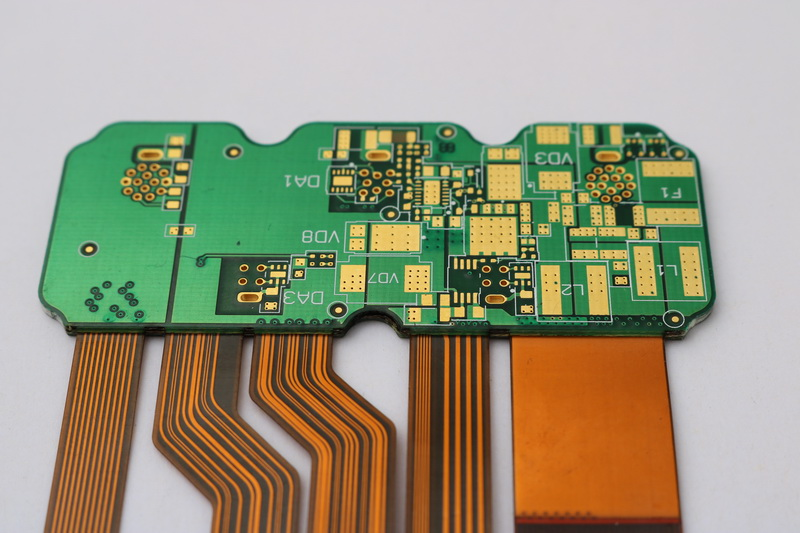
Flex circuits, also known as flexible printed circuits or flex PCBs, are thin, bendable circuit boards made of flexible dielectric materials like polyimide or polyester. They can be bent, folded, twisted, and shaped to fit into tight spaces and move dynamically in electronic devices.
Determining the appropriate thickness for a flex circuit depends on several factors:
Flex Circuit Thickness Considerations
- Electrical performance – Thinner flex circuits allow for finer trace widths and smaller component clearances. Thicker flex circuits can carry more current.
- Mechanical requirements – Thinner flex circuits are more flexible and durable for dynamic bending applications. Thicker flex circuits are more rigid and suited for static installations.
- Component integration – Components add thickness. Flex circuits must be thick enough to allow mounting and clearance of components.
- Manufacturing capabilities – Thinner flex circuits require more advanced specialized processes. Standard flex circuit capabilities range from 0.5mm to 3mm thick.
- Cost – In general, thinner flex circuits are more expensive to manufacture.
Balancing these factors will determine the ideal thickness for a particular flex circuit design and application.
Typical Flex Circuit Thicknesses
Flex circuit thicknesses typically range from about 0.05 mm (0.002″) to over 3 mm (0.12″), but most fall between 0.1 mm (0.004″) to 2 mm (0.08″).
Here are some common flex circuit thickness ranges:
0.05 to 0.1 mm (0.002″ to 0.004″)
Ultra-thin flex circuits in this range provide maximum flexibility and dynamic bending capabilities. They can have very fine trace widths and clearances down to 0.075 mm (3 mils) or less. The thinnest flex circuits can be folded completely flat.
Applications include:
- Wearable devices
- Medical sensors
- Dynamic flexing interconnects
0.1 to 0.2 mm (0.004″ to 0.008″)
Thin flex circuits with excellent flexibility and bend radii. Fine features around 0.1 mm (4 mils) are possible. Often used as dynamic flex interconnects between PCBs or for flexible circuits that require tight bending.
Applications include:
- Foldable/rollable displays
- Wearable devices
- Printer flex circuits
0.2 to 0.5 mm (0.008″ to 0.020″)
Medium thickness flex circuits with good flexibility and durability. Allows trace widths and spaces around 0.2 mm (8 mils) and integration of some components.
Applications include:
- Consumer electronics interconnects
- Automotive flex circuits
- Medical devices
0.5 to 1.0 mm (0.020″ to 0.040″)
Thicker flex circuits with moderate flexibility and component integration capabilities. Allows wider ~0.3-0.5 mm (12-20 mil) traces and clearances.
Applications include:
- Consumer electronics
- Appliance flex circuits
- Automotive sensors
1.0 to 2.0 mm (0.040″ to 0.080″)
Thick flex circuits with minimal bending but ability to integrate many components. Traces can approach 1 mm (40 mil) widths. This thickness approaches rigid-flex circuit boards.
Applications include:
- Component integration and packaging
- Automotive control units
- Industrial electronics
Over 2 mm (Over 0.080″)
Very thick flex circuits with limited flexibility but maximum component integration. Traces up to 2+ mm wide are possible. Often used for static rigid-flex type applications.
Applications include:
- Rigid-flex circuit boards
- Component packaging and integration
Typical Flex Circuit Layer Stackup
In addition to the total thickness, the layer stackup is also an important consideration for flex circuit design.
A typical flex circuit cross-section consists of:
- Cover layer – Protective polymer layer on the top and/or bottom. Usually 12.5 to 25 micrometers thick.
- Conductor layers – Copper traces. From 1 to ~6 metal layers are common for flex circuits.
- Dielectric layers – Flexible insulating polymer material like polyimide between metal layers. From 12.5 to over 100 micrometers thick per layer.
- Bonding adhesive – Thin glue layers that bond the polymer and copper layers. Around 25 micrometers thick per layer.
- Stiffeners – Additional thicker polymer layers like polyimide for rigidity. Often used for components or connectors.
Here are some examples of common flex circuit layer stackups, from simple to complex:
- 2 Layer: Cover layer, single conductor layer, dielectric layer, cover layer
- 4 Layer: Cover layer, conductor, dielectric core, conductor, cover layer
- Multilayer: Cover, conductor, dielectric, conductor, dielectric core, conductor, dielectric, cover
- Rigid-Flex: Cover, conductor, stiffener, dielectric core, multiple conductors, cover
The conductor and dielectric layers make up the majority of the flex circuit thickness. Optimizing the stackup is key to achieving the thinness, flexibility, and reliability required.
Design Rules of Thumb for Flex Circuit Thickness
Here are some general guidelines and rules of thumb to consider when designing flex circuits:
- For dynamic flexing applications, keep overall thickness under 0.2mm. Minimum bend radius is ~10X thickness.
- Match stiffness by varying dielectric material properties and thicknesses across the circuit.
- Use thinner dielectrics for more layers, balancing flexibility and manufacturability.
- Minimize layer count to optimize thickness. Build more complex rigid sections only where needed.
- Place components in rigid sections, avoiding flexible areas. Minimize component protrusion.
- Use solder masking and cover layers to prevent conductor damage at bends.
- Thermal expansion increases with thickness. Manage stresses for reliability.
- Thinner circuits increase manufacturing cost and require tighter tolerances.
- Work closely with your flex circuit manufacturer to understand capability and cost tradeoffs.
- Prototype and test different flex circuit thicknesses for your application requirements.
Following design for manufacturing guidelines and flex-specific layout practices will yield the thinnest workable flex circuit for your particular mechanical and electrical needs.
Flex Circuit Materials by Thickness
Several types of flexible circuit materials are used in different thickness ranges:
Polyimide
Polyimide films like Kapton are the most common flex circuit dielectric. Available in thicknesses from 12.5 to 125 micrometers, polyimide provides an excellent balance of flexibility, heat resistance, and cost. The thinnest polyimide films down to 6 microns can be used for ultra-thin flex applications.
Polyester
PET and PEN polyester films are lower cost than polyimide but have lower maximum temperature ratings. Polyester can be used for flex circuits from 13 to 250 micrometers thick where high temperatures are not required.
LCP
Liquid crystal polymer films like Curv from Rogers Corporation provide a high-performance option for thin flex circuits needing increased rigidity and improved chemical resistance. Typical LCP thickness range is 25 to 100 micrometers.
Thermoset Polymers
Flexible epoxy blends and acrylic adhesives can act as the dielectric for rigid-flex circuits up to several millimeters thick. This allows integrating very thick sections while maintaining some flex capability.
Component Integration with Flex Circuits
Integrating components is a key function of many flex circuits, so the thickness must accommodate the components used.
Here are some guidelines for component integration with flex circuits:
- Place components on rigid sections of the flex circuit whenever possible.
- For flexible areas, use micro-components like chip-scale packages.
- For thin flex circuits, embed bare die or flip chip ICs.
- Keep protruding components to 0.1 mm or less from the surface.
- Avoid placing components in areas with dynamic or tight bending.
- Use flexible solders and adhesives to allow dynamic movement.
- Include standoffs, spacers, or stiffeners to prevent flexing under components.
- Work with your flex circuit manufacturer to match material stackup to components.
Careful design and placement of components enables maximizing the thinness and flexibility of the flex circuit.
Flex Circuit Thickness Testing
Prototyping and testing different flex circuit thicknesses is important to find the ideal tradeoff between flexibility, durability, and electrical performance for the application.
Typical tests include:
Bend radius: Determine the minimum bend radius possible without damage at a given thickness.
Flex testing: Simulate dynamic flexing to validate flex life and characterize stiffness.
Electrical: Measure impedance values, losses, noise, etc. under bending and flexing.
Component integration: Validate assembly processes and reliability with mounted components.
Thermal: Characterize thermal dissipation and effects of expansion/contraction.
Environmental: Assess performance under expected environmental conditions – temperature, humidity, chemicals, etc.
Thorough testing provides the data needed to select the optimal flex circuit thickness and validate the design. Partnering with your flex circuit manufacturer early in the design process is key to getting the specialized knowledge and capabilities to fabricate and test thin flex prototypes tailored to your application requirements.
Conclusion
Determining the right thickness for a flex circuit requires balancing electrical, mechanical, manufacturing, and cost considerations for the particular application. Typical flex circuit thicknesses range from 0.05 mm up to over 2 mm thick. Following design guidelines around layer stackup, bend radius, component integration, and manufacturability will enable creating the thinnest workable flex circuit to meet the demands of the application. Prototyping and testing different flex circuit thicknesses provides vital data to inform the design process. Partnering early with a specialized flex manufacturer skilled in thin flex fabrication is key to optimizing flex circuit thickness for your design.
Flex Circuit Thickness FAQs
What is the thinnest flex circuit available?
The thinnest flex circuits can be as thin as 25-50 microns (0.001″ – 0.002″) for a single layer circuit. Polyimide films are available down to 6 microns to produce ultra-thin multilayer flex constructions. However, 50-100 microns is more typical for a robust commercial thin flex circuit.
How thick should a rigid flex circuit be?
Rigid sections of flex circuits are often 0.2-2.0+ mm thick. This enables integration of multiple layers and components while maintaining some flexible sections. Stiffener layers can be added to create the desired rigidity.
Can components be mounted on thin flex circuits?
Yes, but components should be minimized, placed on rigid areas when possible, and have a very low profile. Special assembly processes like flexible solders and adhesives enable some component integration on thin flex.
What limits how thin flex circuits can be fabricated?
Several fabrication factors limit thinness including minimum trace sizes, registration accuracy, polymer thickness availability, and handling of fragile thin materials. Work with your flex manufacturer to understand limitations.
How do you prevent conductor damage on dynamic thin flex circuits?
Careful design of bend areas along with protective cover coats, solder mask, and/or bonded stiffeners are used to prevent conductor damage in dynamic flexing. Stress relief features can also help prevent cracks.