

An In-Depth Look at Designing and Manufacturing Flexible Printed Circuit Boards
Flexible printed circuit boards (flex PCBs) offer unique advantages over traditional rigid PCBs. Their ability to bend and flex allows them to be used in applications where space is extremely limited. As devices like wearables, medical devices, and consumer electronics continue to shrink in size, the demand for flex PCBs has rapidly grown.
For product developers, integrating a flex PCB into your design requires special considerations during the prototype phase. In this comprehensive guide, we’ll explore the key steps involved in designing, specifying, and manufacturing flex PCB prototypes.
Overview of Flex PCBs
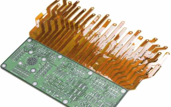
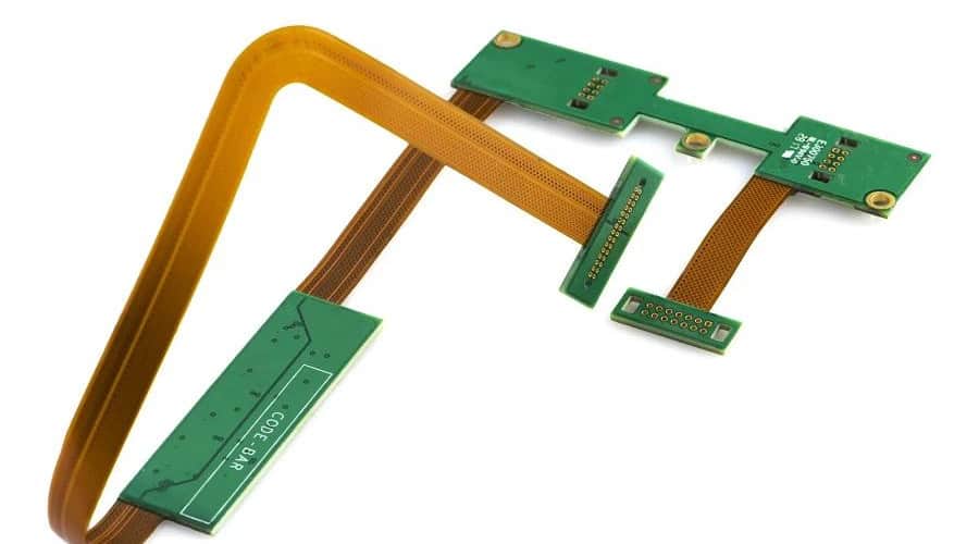
A flex PCB uses a flexible base material like polyimide instead of traditional rigid FR-4. This allows the PCB to bend and conform to different form factors. Here are some key advantages flex PCBs provide:
- Space savings – Can fold and bend to fit in tight spaces
- Flexibility – Can twist and move dynamically without cracking
- Reliability – Excellent shock/vibration resistance
- Lightweight – Very thin and lightweight materials
- High speed – Supports high-frequency signals
Flex PCBs are ideal for wearable devices, medical devices, robotics, folding displays, and any application where flexibility and space savings are required.
Design Considerations
Designing a flex PCB requires special considerations to ensure the circuit can flex reliably without traces cracking or components detaching. Here are some best practices to follow:
Component Placement
- Avoid placing components in high flexing areas
- Use special adhesives for component attachment
- Leave extra space between components
Trace Layout
- Use large bend radii for trace corners (>3x material thickness)
- Place traces in the neutral bend axis, not the extreme edges
- Use stacked vias and redundant connections for reliability
Stiffening Elements
- Add stiffeners made of rigid material to minimize flexing in certain areas
- Use strategically placed openings in the flex layer itself
Layer Stackup
- Use thin flexible dielectric and copper layers
- Minimize the number of layers for maximum flexibility
Following these guidelines will help produce a flex PCB prototype that flexes properly without failure.
Specifying Prototype Requirements
When you’re ready to have flex PCB prototypes manufactured, providing detailed specifications to your PCB manufacturer will ensure you get boards that match your design intent. Here are key details to specify:
Layer Count
- 2 layer, 4 layer, 6 layer? Higher layer counts add rigidity
Board Thickness
- Total thickness including dielectric and copper
Dielectric Material
- Polyimide, PEEK, PET, other? Determines flexibility.
Copper Weight
- 1 oz, 2 oz copper? Thicker copper is more rigid
Minimum Bend Radius
- Specify how tight of a bend the PCB must support
Stiffener Requirements
- Specify any required stiffeners, openings, or flex cuts
Impedance Control
- If needed, specify impedance reqs for high-speed signals
Special Finishes
- Immersion silver, ENIG, etc for wear resistance
Providing these parameters ensures your flex PCB vendor can match the capabilities of your design.
Prototype Manufacturing Process
Now let’s take a look at the manufacturing process used to fabricate flex PCB prototypes:
- Design – The PCB layout is designed in CAD following flex design rules
- CAM Processing – Gerber and drill files are generated
- PCB Fabrication
- Photolithographic processing patterns copper traces
- Etching forms conductors
- Lamination bonds dielectric and foil layers
- Component Assembly – SMT and through-hole parts are assembled
- Testing – Each board is electrically tested and inspected
- Shipping – Prototype boards are shipped directly to the customer
Flex PCB manufacturers use advanced techniques like laser direct imaging (LDI) to pattern fine features on flexible circuits. The key is finding a manufacturer experienced in flex PCB fabrication.
Prototype vs. Production
It’s important to note that the process for manufacturing prototype flex PCBs differs slightly from full flex PCB production:
| Prototyping | Production |
|---|---|
| Small quantities, often 5-10 boards | High volume manufacturing |
| Manual assembly | Automated assembly lines |
| Testing each board individually | Testing statistical samples |
| Higher costs per board | Lower costs for higher quantities |
Prototyping is useful for validating your initial design before moving to full production. Be sure to budget appropriately, as prototype costs are higher.
Finding a Flex PCB Manufacturer
Choosing the right flex PCB manufacturer is key to getting quality prototypes. Here are some tips on selecting a vendor:
- Make sure they have expertise in flex PCB fabrication
- Look for experience with similar flex applications
- Evaluate their design rule guides and capabilities
- Review their quality certifications (ISO 9001, etc)
- Check lead times and costs for prototype quantities
- Ensure they offer design for manufacturing tips
- Validate capabilities with customer reviews and samples
Taking the time to find a reliable flex PCB maker that meets your requirements will ensure a successful prototyping experience.
Flex PCB Prototype FAQ
Here are answers to some frequently asked questions about procuring flex PCB prototypes:
Q: How long does it take to get flex PCB prototypes?
A: For small quantities of 5-10 boards, expect lead times of 1-2 weeks from reputable manufacturers. More complex designs can take 3-4 weeks. Rush turnaround options are sometimes available.
Q: What design tools are used for flex PCBs?
A: Any standard PCB CAD software like Altium Designer, Cadence Allegro, and OrCAD can be used. The designer must follow flex design rules.
Q: Can components be mounted on both sides of a flex PCB?
A: Yes, but components should not be placed in areas that undergo extreme flexing to avoid damage. Use special adhesives to reinforce attachments.
Q: What test and inspection is done for prototypes?
A: Each board should be individually electrically tested. Visual inspection also checks for defects. This verifies the design before production.
Q: How durable are flex PCB prototypes?
A: Properly designed flex prototypes can withstand 100,000+ flex cycles. But extensive testing should be done to qualify the reliability over the product lifetime.
Conclusion
Designing and prototyping a flex PCB requires special care and expertise. By following flex design guidelines, providing complete specifications, and finding an experienced manufacturer, you can obtain high-quality flex PCB prototypes to validate your design. Remember to budget appropriately and work closely with your supplier to get boards that meet requirements. With an iterative prototyping approach, you can perfect your flex PCB design before moving into production.