

Introduction
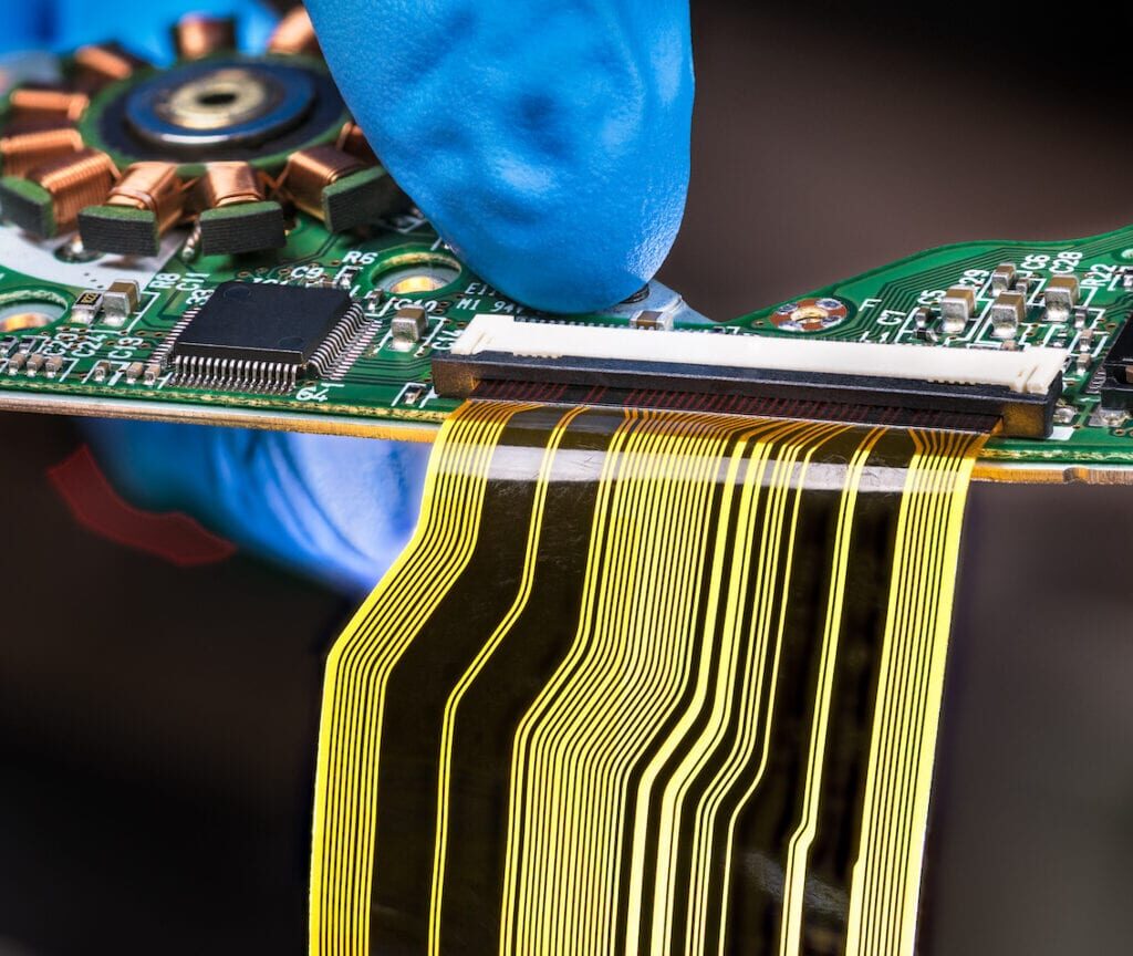
A rigid-flex printed circuit board (PCB) is a special type of PCB that combines rigid and flexible PCB technologies into a single circuit board. Rigid-flex PCBs provide the ability to interconnect multiple rigid circuit boards using flexible circuits, allowing three-dimensional packaging and routing of circuits. This enables more compact and lightweight electronic devices and improved reliability compared to using connectors and cables. Rigid-flex PCBs have wide applications in consumer electronics, telecommunications, military, aerospace, medical devices and other areas.
Key Applications of Rigid Flex PCBs
Here are some of the most common applications of rigid flex PCB technology:
1. Consumer Electronics
Rigid-flex PCBs are widely used in various consumer electronic devices where space is limited and flexible interconnections are required. Typical applications include:
- Cell phones – To interconnect multiple PCBs and components in a compact folding phone design. Allows routing signals through hinges.
- Laptops – To interconnect motherboard and display PCBs and route signals through the hinge. Provides stress relief.
- Digital cameras – To connect CCD, controller, memory and display boards in a confined space.
- Wearables – To create flexible circuits that can conform to the human body.
2. Automotive Electronics
In automotive applications, rigid-flex PCBs are used to:
- Create electronic control units (ECU) with rigid and flexible sections to fit in tight spaces
- Interconnect PCBs in different zones of the vehicle using flexible circuits
- Improve reliability by reducing connectors and cables that can fail due to vibration and temperature changes
3. Aerospace and Military
The lightweight and reliable nature of rigid-flex PCBs make them suitable for:
- Guidance, navigation and control systems in missiles and satellites
- Avionics equipment where size and weight reduction is critical
- Rugged electronic systems for military, aerospace and defense applications
4. Medical Equipment
In medical devices, rigid-flex PCBs provide:
- Flexible interconnects for sensors, transducers and electrodes
- Ability to fit circuit boards into small, curved spaces
- MRI gradient coils and ultrasound transducers
- Implantable medical devices
5. Instrumentation
Rigid-flex PCBs are often used in test and measurement equipment to:
- Connect multiple boards and route signals
- Allow dense, efficient 3D stacking of circuitry
- Withstand vibration and repeated flexing
- Common in oscilloscopes, logic analyzers, signal generators etc.
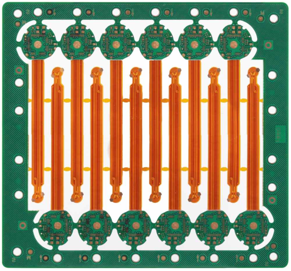
Rigid-Flex PCB Construction
Rigid-flex PCBs integrate flexible circuits and rigid boards using special design and manufacturing processes. Here are some key aspects of their construction:
- The rigid sections are typically made of standard FR-4 PCB material.
- The flexible sections use polyimide or other flexible polymer films like Kapton.
- Adhesive layers bond the flexible and rigid sections together.
- Flexible layers are usually single or double sided circuits.
- Special rigid-flex materials like thermal stable flexible materials are sometimes used.
- Smallest bend radius ranges from 2 to 10 times the thickness of the flex circuit.
- Vias and components are only located on rigid sections.
- Shielding, stiffeners and covers are often used for protection.
| Layer | Typical Thickness |
|---|---|
| Copper traces | 1⁄2 oz (18 μm) to 2 oz (70 μm) copper foil |
| Polyimide flexible substrate | 12.5 μm to 75 μm |
| Adhesive | 25 μm to 50 μm |
| Rigid FR4 substrate | 100 μm to 1.6 mm |
Benefits of Rigid Flex PCBs
Here are some of the major benefits provided by rigid-flex PCB technology:
- Compact design – Integrates multiple PCB assemblies into a single board with 3D layout and folding. Enables miniaturization.
- Flexibility – Literally and figuratively! Flex circuits provide stress relief and conformability.
- Reliability – Eliminates connectors and cables that can fail. Provides vibration resistance. Withstands flexing.
- Weight reduction – Thinner and lighter than using separate rigid boards and connectors.
- High-speed performance – Impedance control and material stability supports high frequency signals.
- Design freedom – Allows unique form factors, folding and curving PCBs.
- Reduced assembly cost – Decreases number of components and connectors for lower assembly cost.
Types of Rigid-Flex PCBs
There are several design variations of rigid-flex PCBs to suit different applications:
1. Flex-rigid – Flexible circuit with localized rigid sections at component locations. Used for dynamic flexing applications.
2. Rigid-flex-rigid – Multiple rigid boards interconnected by flexible circuits. Allows 3D stacking and folding.
3. Rigid multilayer flex – Flex circuit with multiple conductive layers. Used for space constrained interconnects.
4. Multilayer rigid-flex – Combination of multilayer rigid boards and flex circuits. Enables integration of high density circuits.
5. Sculptured rigid-flex – Flex circuits folded into complex 3D shapes. Permits unusual form factors.
6. Moving rigid-flex – Rigid and flex sections designed for controlled movement. Used in hinges and joints.
7. Backplane rigid-flex – Interconnects multiple boards for high speed data transmission. Used in servers and network gear.
Design Considerations
Rigid-flex PCBs require special design considerations:
- Ensure minimum bend radius is maintained in flex areas.
- Avoid components, vias, and traces in the bend areas.
- Use teardrop pads at junction of rigid and flex to avoid stress cracks.
- Design stackup for balance, controlled impedance, and adhesion.
- Analyze dynamic, static, and shock and vibration loads on the flex circuits.
- Use guidelines specific to your PCB manufacturer’s process capabilities.
Careful thermal and mechanical modeling is advised to assess reliability over the life of the product.
Manufacturing and Assembly
Rigid flex PCBs require specialized fabrication processes:
- Photolithography process must align layers across rigid and flex sections.
- Etching processes require special fixturing for dealing with the mixture of rigid and flexible materials.
- Laser direct imaging is now commonly used for improved alignment and feature control.
- Lamination process requires accurate heating, pressure and flatness across dissimilar materials.
- Automated optical inspection (AOI) systems are critical for process control over rigid and flex regions.
- Special fixtures are needed for PCB routing, with variable depth for cutting rigid and flex zones.
- Board assembly may require creative solutions to adapt to the folded 3D shape.
Quality Control
Several quality tests are essential to ensure reliability:
- Visual inspection of conductor alignment between rigid and flex layers
- Cross sectional analysis to verify layer alignment and bonding
- Automated inspection of minimum line/space dimensions
- Flex fold and dynamic fatigue testing via repeated bending
- Environmental stress testing for thermal shock, moisture resistance etc.
- Detailed functional testing in application conditions
- Analysis of failed boards for root cause investigation
Future Trends
Some emerging trends that will shape rigid flex PCB technology include:
- Narrowing interconnects below 100 microns to increase flex circuit density
- Expanding adoption of rigid-flex in automotive and medical applications
- Use of flexible hybrid electronics which combine ICs in flexible circuits
- Incorporating printed electronics technologies like inkjet and aerosol printing
- Shift to lower-cost laser direct imaging from older photolithography processes
- Increased simulation and modeling to optimize designs and reliability
- Additive manufacturing and metal 3D printing for flexible circuit fabrication
Conclusion
Rigid flex PCB technology enables the integration of multiple PCB assemblies into more compact, lightweight and reliable electronic products. With their inherent flexibility and adaptability, rigid-flex PCBs will continue to see strong adoption across a wide range of industries and applications that demand miniaturization, performance and robustness. Continued improvements in design tools, manufacturing capabilities and materials science will open up new possibilities for product development with this unique circuit integration platform.
Frequently Asked Questions
Q: What are some typical capabilities of rigid flex PCB manufacturers?
A: Typical capabilities include:
- Rigid board thickness from 0.4mm to 3.2mm
- Flex layer thickness down to 12 microns
- Line width/spacing down to 100/100 micron (4/4 mil)
- Layer counts up to 30+
- Flex-to-rigid ratio from 100% flex to 100% rigid
- Quick-turn prototyping in 5 days
- Small to medium production volumes (e.g. 10 boards to 10,000 boards)
Q: What types of materials are commonly used?
A: Common materials include:
- Rigid sections: FR-4, high Tg FR-4, halogen-free FR-4, ceramic-filled PTFE
- Flexible substrates: Polyimide (Kapton), adhesive-coated polyimide, LCP, PEN, PET
- Bonding adhesives: acrylic, modified acrylic, nitrile phenolic
- Cover layers: Polyimide, PET, acrylic
Q: Can components be assembled on both rigid and flex sections?
A: Typically components are only assembled on rigid portions of the PCB. The flexible areas are usually limited to traces and pads only. Discrete components can fracture or detach during flexing.
Q: What are some key inspection criteria for acceptability?
A: Key inspection criteria:
- Trace integrity and no signs of cracking
- No delamination between bonded layers
- No measling, crazing, blistering of dielectric
- No significant smear, bulge, or wrinkles
- No shorts, opens, impedance mismatches
- Pass electrical testing and functional eval
Q: How are rigid flex PCBs typically tested?
A: Typical tests performed:
- Visual inspection at all stages of fabrication
- IPC Class 2 and 3 requirements for trace/space
- Cross-section analysis
- Netlist testing for connectivity
- Impedance, insertion loss, VSWR for controlled impedance traces
- HASS, temperature cycling, vibration testing
- Static and dynamic flexure testing
- Functional testing in operation conditions
Article Highlights
- Rigid flex PCBs integrate rigid boards and flexible circuits into a single assembly.
- Widely used in consumer electronics, automotive, aerospace, medical and instrumentation fields.
- Combines 3D layout and folding with flexible signal routing.
- Key benefits are compact size, improved reliability, design freedom.
- Requires careful design to avoid component placement in flex areas.
- Manufacturing processes must align layers across mixed materials.
- Quality control essential via inspections, testing, reliability studies.
- Continued improvements in technology opening up new applications.