

Rigid flex printed circuit boards (PCBs) represent an exciting innovation in printed circuit board design, combining the stability and structure of a rigid PCB with the dynamic flexibility of a flex circuit. With the ability to bend and fold into three-dimensional configurations, rigid flex PCBs enable creative solutions to complex electronic packaging problems across a wide range of applications, from consumer electronics to aerospace systems.
What is a Rigid Flex PCB?
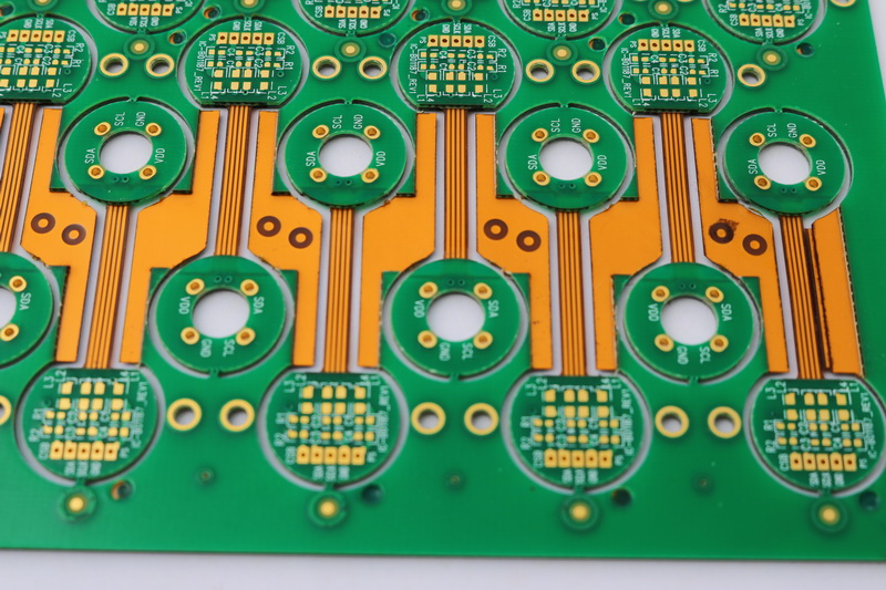
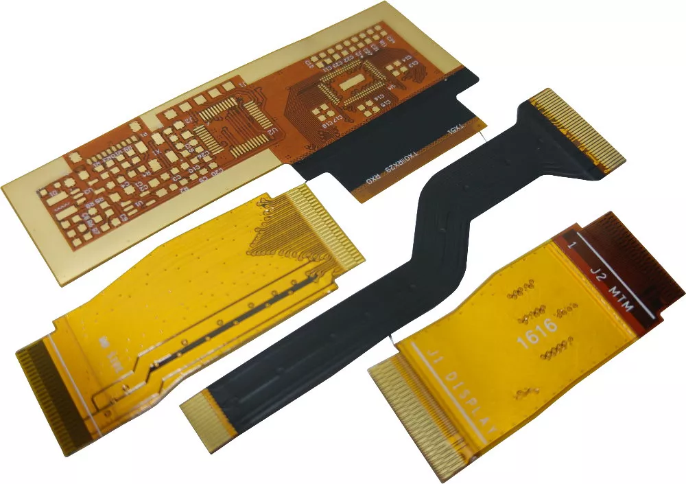
A rigid flex PCB consists of rigid sections interconnected by flexible sections of dielectric material and traces. The rigid sections provide mechanical stability and component mounting surfaces, while the flex sections allow dynamic movement and three-dimensional configuration. Rigid flex PCBs provide the ideal combination of rigidity and flexibility in a single PCB structure.
Some key properties of rigid flex PCBs:
- Combines rigid and flexible materials into a single PCB structure
- Enables flexible bending and folding while maintaining board stability
- Flexible sections consist of thin flexible dielectric layers with conductive traces
- Rigid sections consist of standard rigid PCB laminates
- Components mount on the rigid sections
- Flex sections bend dynamically to allow 3D configuration
- Offers weight, space, and wiring reduction compared to connectors and cables
- Ideal for complex layouts in tight spaces
Benefits of Using Rigid Flex PCBs
Rigid flex PCBs provide a number of important benefits compared to traditional rigid PCBs or flex circuits alone:
Flexible Movement and Configuration
The flexible sections of a rigid flex PCB allow the board to bend, fold, and conform to unique mechanical configurations and movements. The PCB can be dynamically reconfigured as needed to optimize the electronics layout for complex geometries and tight spaces.
Reduced System Size and Weight
By integrating flexible and rigid sections into a single PCB structure, rigid flex technology eliminates the need for separate rigid boards connected by wire harnesses and connectors. This reduces overall system size and weight.
Enhanced Reliability
With fewer separate components and connections, rigid flex PCBs offer improved mechanical life and reliability compared to wired connections between rigid boards. The rugged flexible material also withstands vibration and flexing stresses.
Design Flexibility
Rigid flex PCBs allow much more freedom and creativity in electronics layout and configuration compared to rigid technology alone. The design can be optimized around mechanical features and tight spaces.
Reduced Assembly Cost
Automated assembly and soldering is simpler with a consolidated rigid flex board, reducing production cost compared to assembling separate rigid boards and wire harnesses.
In summary, rigid flex PCBs offer an array of size, weight, complexity, reliability, assembly, and design advantages over traditional approaches. This makes them an extremely powerful solution for many modern electronic systems.
Rigid Flex PCB Construction and Materials
Rigid flex PCBs feature specially engineered construction and materials to provide the desired combination of flex and rigidity:
Layer Stackup
A cross-section of a typical rigid flex PCB reveals the specialized layer stackup:
- Rigid core layers form the foundation. Common rigid laminates include FR-4 and polyimide.
- Flexible dielectric layers made of polyimide are bonded to the rigid cores.
- Adhesive layers bond the rigid and flex layers.
- Copper traces are etched on both rigid and flexible layers. Traces extend continuously between both sections.
- Additional covering layers protect the traces.
Flexible Dielectric Materials
The flexible sections of the PCB use durable, thin polyimide dielectric layers. Common flexible dielectric films include:
- Kapton – Dupont branded polyimide film
- UPILEX – Ube branded polyimide film
- APICAL – Kaneka branded polyimide film
These provide the necessary combination of flexibility, heat resistance, chemical resistance, and dimensional stability. Polyimide films around 25-100μm thick are typical.
Rigid Dielectric Materials
The rigid sections of the PCB use traditional rigid laminate dielectrics. Common options include:
- FR-4 – brominated glass reinforced epoxy
- BT (bismaleimide triazine) – glass reinforced thermoset
- CE (cellulose paper) – cellulose fiber reinforced thermoset
- Polyimide – glass reinforced thermoset polyimide
Bonded Layer Interface
Bonding the layers together presents challenges. Adhesive layers securely join the flexible and rigid sections. Acrylic, epoxy, or thermoplastic adhesives are commonly used.
Careful design of the layer stackup and robust bonding are critical to ensure reliability.
Rigid Flex PCB Design Considerations
Rigid flex PCB design requires attention to the following special considerations:
Layer Stackup Design
- Select suitable flexible films and rigid laminates
- Choose number of layers and dielectric thicknesses
- Design adhesive layers for bonding flex and rigid sections
- Ensure suitable dielectric properties, thickness, and lamination strength
Reliable Flex-to-Rigid Transitions
- Avoid sharp corners and transitions in traces between flexible and rigid sections
- Use rounded corners and teardrop shapes for smooth transitions
- Minimize rigid-flex interface misalignment during bending
Trace Design in Flexible Areas
- Use narrower traces than on rigid sections
- Wider trace spacing required in flex areas
- Account for dynamic flexing forces on traces
- Ensure traces do not overheat when flexed
Component Placement
- Place components only on rigid sections
- Avoid placing components in areas of dynamic flexing
- Watch component spacing as board is flexed
Board-Level Simulation
- Simulate mechanical stresses during flexing and bending
- Verify electrical performance with dynamic bending
- Thermally simulate effects of component heating during flexing
Design Rule Development
- Establish design rules for trace geometry on flex layers
- Define minimum bend radius and flex limits
- Set guidelines for rigid-flex section interfaces
- Develop rules for component placement near bend areas
Careful attention during design is necessary to create a reliable, high performance rigid flex PCB.
Applications of Rigid Flex PCBs
With their unique ability to integrate complex flexibility with rigid stability, rigid flex PCBs are ideal for many advanced electronics designs across diverse markets:
Aerospace and Defense
High reliability, tight space constraints, and vibration resistance make rigid flex PCBs suitable for many aerospace applications. Used extensively in guidance systems, engine controls, satellites, and radar systems.
Automotive Electronics
Rigid flex PCBs withstand vibration while fitting into tight spaces and complex geometries within vehicles. Used for engine control units, lane departure warning systems, vehicle stability controls, and drive-by-wire systems.
Consumer Electronics
Folding and compact configuration benefits rigid flex PCBs in mobile phones, tablets, wearables, drones, and virtual reality systems to save space and enable portability.
Medical Equipment
Tightly packaged medical devices like endoscopes, surgical robots, and hearing aids benefit from rigid flex PCBs’ ability to fold into compact medical equipment geometries.
Industrial Electronics
Space constrained industrial applications like robotics, CNC machines, and motion control use rigid flex PCBs for reliable electronic control.
LED Lighting
Complex LED lighting fixtures use rigid flex PCBs to conform to curved surfaces and structures.
With new applications constantly emerging, rigid flex PCBs will continue driving a revolution in electronic device construction, packaging, and reliability.
Rigid Flex PCB Assembly Considerations
Assembling components onto rigid flex PCBs requires adaptations of standard assembly processes:
Component Placement
- Components only assemble onto rigid sections
- Ensure sufficient clearance from flexed areas
- Avoid placing components in highly dynamic flex areas
- May require smaller or special components near flex regions
PCB Handling and Fixturing
- Need to develop handling and fixturing methods for fragile flexing areas
- Carrier frames or special clamping required
- Allow for repositioning rigid sections during assembly steps
Soldering Processes
- Reflow soldering is preferred
- Manual soldering requires specialized fixturing
- Ensure thermal stresses do not damage flexible areas
Cleaning
- Avoid chemical exposure of flexible regions
- Cleaning processes may require modifications or special fixturing
Conformal Coating
- Select flexible coatings able to withstand bending
- Mask flexible sections during coating of rigid areas
- Apply coating strategically to only protect needed regions
Inspection
- Must visually inspect along flexible bends
- X-ray allows inspecting hidden flexible areas
- Automated optical inspection requires special fixturing
With planning, the necessary adaptations are straightforward. Rigid flex PCB assembly leverages many of the same principles and processes as standard PCB assembly.
The Future of Rigid Flex PCB Technology
Rigid flex PCBs are currently experiencing rapid growth as their advantages become widely recognized. However, the technology still has room for improvement as processes and materials continue evolving:
- Improved Flexible Materials – New flexible dielectric films and adhesives with enhanced properties and performance. Films like liquid crystal polymer (LCP) increase heat resistance and signal speed.
- Fine Line Flex Circuits – Improved processes to produce even finer lines and spaces to increase rigid flex PCB density and complexity. Lines/spaces below 25 μm are becoming possible.
- Advanced Rigid-Flex Interconnection – Better structural solutions and materials science to improve mechanical reliability of transitions between rigid and flex sections.
- More Robust Flexible Circuits – Processes to produce more layers in flexible sections along with higher density traces and vias spanning rigid-flex boundaries.
- Design Tool Improvements – More simulation capability to virtually prototype rigid flex PCB system reliability considering thermal, mechanical, and electrical effects.
- Cost Reduction – Continued improvement in fabrication processes and economies of scale to reduce rigid flex PCB costs and make them accessible to lower volume applications.
As technology continues progressing, we can expect rigid flex PCBs to enable transformative electronics solutions we can only begin to imagine today.
Frequently Asked Questions About Rigid Flex PCBs
Here are answers to some common questions about rigid flex PCB technology:
What is the typical minimum bend radius for a rigid flex PCB?
The minimum bend radius depends on the construction, but is typically around 5 times the total board thickness for flex sections. With careful design, some constructions can bend to 3x board thickness.
Can components be mounted directly on the flexible section?
Generally no – components should only be mounted on rigid sections to avoid mechanical stresses. However, some small durable components may be possible with proper design.
What are some key considerations when designing rigid flex?
- Accounting for dynamic mechanical stresses during movement
- Trace geometries optimized for flexible sections
- Managing layer stackup and lamination for strength
- Highly reliable rigid-flex section interfaces
- Efficient simulation and prototyping to perfect the design
What types of materials are used in rigid flex PCBs?
- Rigid sections use traditional materials like FR-4 or polyimide laminates.
- Flexible sections use polyimide films like Kapton or UPILEX.
- Adhesives like acrylic or thermoplastics join the layers.
- Copper foils form the traces.
How are components assembled on rigid flex PCBs?
Soldering to rigid sections uses normal SMT assembly processes. But handling flexible sections during production requires specialized tooling and control of thermal impacts.
Conclusion
With the capability to dynamically fold and configure, rigid flex PCB construction provides revolutionary design flexibility compared to traditional rigid boards. The integration of rigid and flexible materials into a singular PCB unlocks innovations across a broad range of electronics applications. As material science and fabrication processes continue advancing, we can expect wider adoption of rigid flex technology and the novel products it makes possible. With diligent design tailored to the unique requirements of combining rigid stability and flexible movement, engineers leveraging rigid flex PCBs will create tomorrow’s transformative electronic devices.