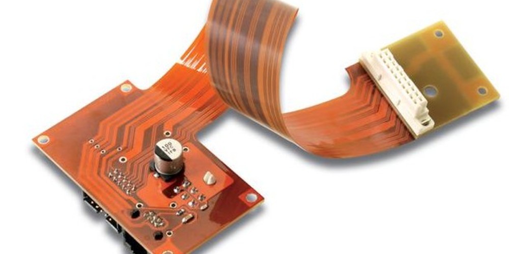
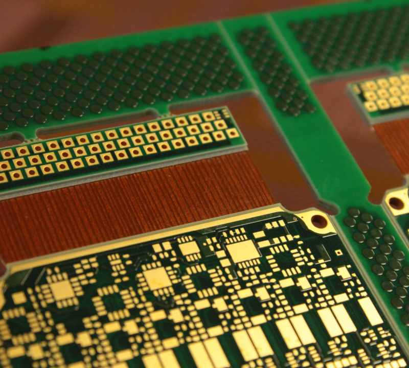
Flexible printed circuit boards (flex PCBs) have become increasingly popular in recent years due to their ability to bend and flex to fit constrained spaces in electronic devices. But how thick are flex PCBs? The thickness can vary quite a bit based on the number of conductive layers and type of material used.
Typical Thickness Ranges
Single Layer Flex Circuits
For simple flex circuits with just a single conductive layer, the thickness typically ranges from 25 to 75 microns (1 to 3 mils). This thin profile is ideal for fitting into the tightest spaces and allowing dynamic flexing motions. Some key examples:
- 25 microns (1 mil) – ultra thin circuits ideal for dynamic flexing
- 50 microns (2 mils) – standard single layer flex thickness
- 75 microns (3 mils) – robust single layer flex for more rigidity
Two Layer Flex Circuits
With two conductive layers, the thickness increases to allow for the additional layer. Typical thicknesses for two-layer flex PCBs are:
- 50 microns (2 mils) – thin two layer flex
- 75 microns (3 mils) – standard two layer flex
- 100 microns (4 mils) – more durable two layer flex
So in summary, two layer flex PCBs tend to range from 50 to 100 microns (2 to 4 mils) in thickness. The second layer provides more rigidity.
Multilayer Flex Circuits
For more complex flex circuits with 3 or more conductive layers, the thickness increases further. Common thicknesses are:
- 125 microns (5 mils) – 3 layer flex circuit
- 150 microns (6 mils) – 4 layer flex circuit
- 200 microns (8 mils) – 6 layer flex circuit
In general, multilayer flex PCBs range from 125 to 200 microns (5 to 8 mils) depending on the number of conductive layers required. The additional layers provide more rigidity for the multilayer board.
Thickness Factors
Several factors influence the overall thickness of the flex PCB beyond just the number of layers:
Copper Weight
The copper thickness used for the conductive traces impacts the overall thickness. Thinner copper reduces thickness. Common copper weights are:
- 1/4 oz (8.5 microns) – ultra thin and flexible
- 1/2 oz (17 microns) – standard flexible copper thickness
- 1 oz (34 microns) – more durable for flexing
- 2 oz (68 microns) – thick copper for maximum durability
Coverlay Thickness
The coverlay is the protective coating layer over the top and bottom of the flex circuit. Thinner coverlay reduces overall thickness. Common coverlay thicknesses are:
- 25 microns – thin for better flexibility
- 50 microns – standard thickness
- 75 microns – thick coverlay for ruggedness
Base Material Thickness
The base polyimide layer also impacts thickness. Typical thicknesses are:
- 25 microns – ultra thin base material
- 50 microns – standard flex circuit base thickness
- 75 microns – thick base for maximum rigidity
Adhesives
The adhesive layers between layers will also add to the overall thickness. Adhesive thickness is typically around 25 microns.
By optimizing these thickness factors, flex circuit manufacturers can fine tune the overall thickness of the flex PCB for the particular application.
Thickness Tolerances
In terms of tolerances, flex circuit thickness typically has the following control:
- Single Layer Flex – +/- 13 microns
- Two Layer Flex – +/- 20 microns
- Multilayer flex – +/- 26 microns
So the actual thickness is usually very close to the nominal thickness for flex PCBs. Flex circuit makers use advanced lamination presses to tightly control the overall thickness during fabrication.
Flex Circuit Bend Radii
An important point is that the thickness also influences the minimum bend radius. Thinner flex circuits can bend tighter than thicker boards. Some typical minimum bend radii based on thickness:
- 25 microns – Bend radius of 2mm
- 50 microns – Bend radius of 3mm
- 75 microns – Bend radius of 5mm
- 100 microns – Bend radius of 7mm
So in tight spaces where flex circuits need to fold frequently, thinner constructions are desired to allow tight bending without damage.
Thickness vs. Rigidity and Reliability

While thinner flex circuits provide the highest degree of flexibility, sometimes more rigidity and reliability are needed. Key trade-offs to consider:
- Thinner flex PCBs can dynamically flex more but provide less rigidity
- Thicker flex PCBs are more rigid but can’t bend as tightly
- Thinner circuits are prone to damage during assembly and use
- Thicker circuits are more durable but may not fit small spaces
So the ideal thickness is a balance between flexibility, durability, assembly yield, and fit within the design space.
When Thinner is Better
Here are some examples where a thinner profile is advantageous:
- Inside hinged electronics like laptops and flip phones
- Between folded display panels
- Interconnections between boards in a stacked configuration
- Circuitry wrapping around cylinders orgiving shapes
- Wearable electronics that need to flex with body movements
Thinner flex circuits truly shine for these dynamic applications.
When Thicker is Better
Some examples where thicker flex can be beneficial:
- Circuits with many layers and high component density
- Mission critical circuits where reliability is paramount
- Circuits exposed to frequent handling and abuse
- Flex-to-board connections where rigidity aids assembly
- Static flex circuits that do not need dynamic bending
Here the extra rigidity and durability of thicker flex PCBs helps optimize performance.
So in summary, carefully consider the trade-offs when selecting flex circuit thickness for your particular design requirements.
Key Considerations When Selecting Flex PCB Thickness
Flexibility
How tight of a bend radius is needed? Thinner flex can fold tighter.
Rigidity
Is stiffness important? Thicker flex is more rigid.
Reliability
Will the circuit experience vibration or shock? Thicker flexes withstand more abuse.
Layer Count
Are multiple conductive layers needed? More layers increase thickness.
Durability
Will the circuit be exposed to frequent handling? Thicker coverlay and base help.
Assembly Yield
Is the circuit high density? Thinner flex can be harder to assemble without damage.
Fit
Is space extremely constrained in the product? Thinner profile may be required.
Dynamic Flexing
Does the circuit need to move or contour often? Thinner flex folds easier.
Static Positioning
Is the circuit held in a fixed arrangement? Thicker flex provides more rigidity.
Frequently Asked Questions
How thick are flex PCBs typically?
Flex PCB thickness ranges from 25 microns for single layer circuits up to 200 microns for multilayer circuits. The most common thickness is around 50-75 microns (2-3 mils).
What is the thinnest flexible PCB available?
The thinnest standard flex PCB is around 25 microns (1 mil) which is used for dynamic flexing applications requiring tight bend radii. With special materials and processes, flex PCBs of 12 microns are possible but less common.
What is a normal flex PCB thickness?
The typical flex PCB thickness used for many consumer electronics and other applications is 50 microns (2 mils). This provides a good balance of flexibility and durability for mainstream flex circuit designs.
How thick are rigid flex PCBs?
Rigid-flex PCBs have flexible areas typically around 50-100 microns connected by more rigid sections of 1-2 mm thickness. So rigid-flex has both thin flexible zones and thicker rigid segments.
Does thinner flex PCB thickness increase cost?
Yes, fabricating thinner flex circuits often requires more expensive base materials, thinner copper, and specialized processes which increases cost. But the reliability and performance gains of thin flex can justify the additional expense.
Conclusion
Flex circuit thickness is an important design consideration affecting flexibility, durability, assembly yield, and overall performance. Carefully evaluate the trade-offs when selecting the thickness for your particular design requirements and application. With the proper thickness, flex PCBs can maximize reliability and capability within the tightest spaces and most demanding flexing environments.


