Introduction
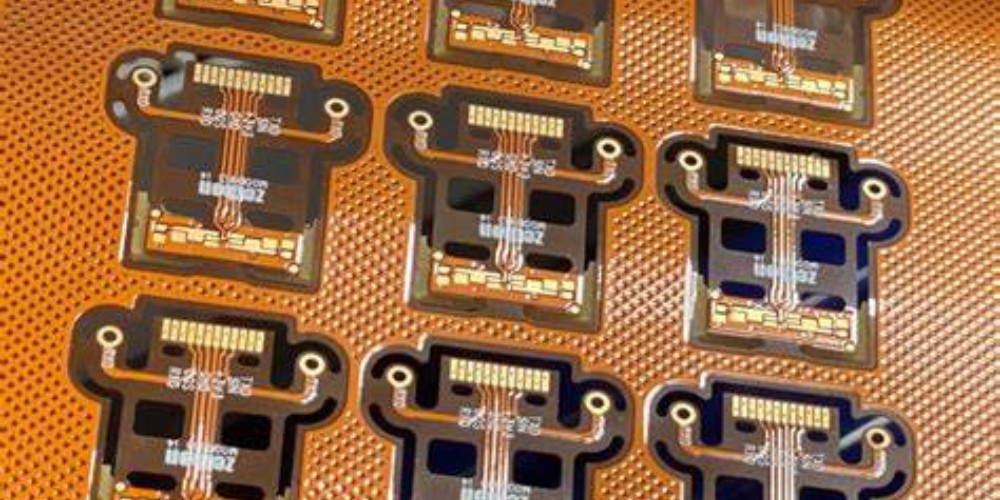
Flexible circuit boards, also known as flex circuits, are a type of printed circuit board made from flexible materials such as polyimide or polyester films. Unlike traditional rigid circuit boards, flexible circuit boards can bend and flex while still maintaining their electrical connections. This ability to dynamically change shape makes flexible circuit boards well-suited for use in small, movable electronic devices. Flex circuits are widely used in consumer electronics, automotive, aerospace, medical devices and more.
How Flexible Circuit Boards Work
A flexible circuit board consists of a thin insulating flexible substrate onto which conductive pathways or traces are printed using techniques like screen printing. The substrate provides a base for the circuitry and helps prevent shorts and current leakage between traces. The conductive traces are often made from copper or other metals and carry signals between different components mounted on the flex circuit board. Components are attached to contact pads along the traces. Flexible boards can have connections on one or both sides. Vias or plated through holes are used to connect traces between layers for double sided boards.
Flexible circuit boards achieve their bend and flex through the use of thin, pliable substrate materials. Common substrates include:
- Polyimide: A thermoset plastic material that offers excellent heat resistance, chemical resistance and mechanical strength. The most commonly used flexible circuit board material.
- Polyester: A thermoplastic material that is more economical than polyimide but has lower maximum temperature ratings.
- PEN: Polyethylene naphthalate plastic with good chemical resistance.
- PET: Polyethylene terephthalate films used in lower complexity flex applications.
- LCP: Liquid crystal polymer substrates with excellent high frequency signal performance.
Cross-Section and Layer Structure
The cross-sectional layer structure of a flexible circuit board is illustrated below:
| Layer | Description |
|---|---|
| Conductive Metal Traces | Usually copper, forms the conductive pathways |
| Substrate Material | Flexible plastic film that forms the base |
| Adhesive | Joins layers together in multilayer boards |
| Coverlay | Protective top layer coating |
Flexible boards can be single sided, double sided or multilayer. Complex flex circuits may contain many layers stacked and interconnected to provide robust connectivity in a compact, bendable package.
Benefits of Flex Circuits
There are several key advantages that make flexible circuit boards a useful alternative to rigid printed circuit boards:
- Flexible: Can bend, twist and flex without damage to traces. Enables conformal fitting and dynamic flexing.
- Lightweight: Thin, lightweight construction compared to rigid boards.
- Durable: Withstands vibration, shock and flexing.
- Compact: Thin profiles allow compact, space saving PCB solutions.
- High Density: Small traces and close spacing provides high component density.
- Reliable: Proven technology with excellent electrical performance.
Flex circuits are ideal when the application demands dynamic movement, tight space constraints, light weight or ruggedness. The lack of rigid framing also reduces weight. The ability to wrap and mold flex circuits to fit unique shapes allows for innovative, compact and portable electronic package designs.
Flexible Circuit Board Applications

Thanks to their bendable construction and reliability, flexible circuit boards have proven useful across a wide range of applications:
Consumer Electronics
Flex circuits are extensively used in modern consumer electronics like smartphones, tablets, wearables, game consoles and more. Flexible interconnects are ideal for folding or sliding mechanisms like flip phones or laptop lids. They also allow packing electronics into ever-smaller product enclosures. Common uses in consumer electronics include:
- Displays
- Batteries
- Hinges
- Buttons
- Sensors
- Cameras
Automotive
Vehicles make use of flex circuits for dashboard electronics, engine controls, in-car entertainment, lighting, sensors and other automotive subsystems. Benefits include resistance to vibration, proven reliability and lighter weight compared to cabling harnesses. Automotive applications include:
- Instrument panels
- Engine control units
- HVAC controls
- Automatic door and window mechanisms
- Car stereos and infotainment systems
- Lane departure warning systems
- Blind spot detection sensors
Medical
Healthcare and medical devices use flexible circuits in applications where flexibility, reliability and biocompatibility are important. Flexible printed circuits are well-suited for use inside the human body. Medical uses include:
- Hearing aids
- Pacemakers
- Blood glucose monitors
- Endoscopes
- Catheters
- Surgical devices
Aerospace and Defense
Rugged flexible circuit boards withstand mechanical stress and vibration in aerospace systems. Light weight construction is also beneficial for air and spacecraft. Typical aerospace applications:
- Avionics equipment
- Flight control systems
- Satellite mechanisms
- UAVs and drones
- Missile guidance systems
Industrial
The range of industrial uses for flexible circuit boards includes robotics, instrumentation, controls, sensors, power electronics and more. Benefits like compact size, dynamic flex cycles and vibration resistance are valued in factory automation and other industrial settings.
Flexible Circuit Board Design Considerations
When designing flex circuits, engineers need to account for the mechanical demands of dynamic flexing that will occur in the intended application. Key design factors include:
- Bend radius: Avoid sharp folds that exert high stress and strain on traces. Maintain bend radius above minimums.
- Conductors: Use copper alloys like rolled annealed or ED copper to improve flexure tolerance.
- Substrate material: Select polyimide, polyester or other flexible films suited to the expected flexing.
- Adhesives: Use flexible adhesive materials like acrylic or epoxy for multilayer boards.
- Reinforcement: Add stiffeners or appliques to flex areas needing additional support.
- Termination: Provide strain relief for trace connections to heavier components.
- Dynamic flex: Design for lifecycle flexing, fatigue and repeated bends.
Proper mechanical analysis ensures the flex circuit can withstand the required dynamic environment without failure or degraded performance.
Flexible Circuit Board Manufacturing
Specialized manufacturing techniques have been developed to produce high quality flex circuits and maintain tight tolerances. Production involves the following steps:
Imaging
A photosensitive layer is applied to the substrate material to allow photolithographic patterning of the desired circuit layout.
Etching
Unwanted areas are chemically etched away to leave only the desired copper traces.
Plating
Traces are plated with metals to achieve desired thickness and coatings.
Coverlay
A protective heat-activated epoxy coverlay coating is applied over the substrate and traces. Openings are made for solder pads and components.
Assembly
Components are precisely placed and soldered to the prepared flex board.
Testing
Electrical testing validates proper connections and ensures the board functions as intended.
With expertise in specialized flexible PCB processes, manufacturers can reliably produce complex flex circuits at scale.
Future Outlook for Flexible Circuit Boards
Several technology trends are driving increased demand for flex circuits and opening up new capabilities:
- Growing adoption in consumer electronics and wearables.
- Development of flexible OLED and e-paper displays.
- Flexible thin film solar cells and batteries.
- Printed electronic inks allowing embedded flex circuitry in product enclosures.
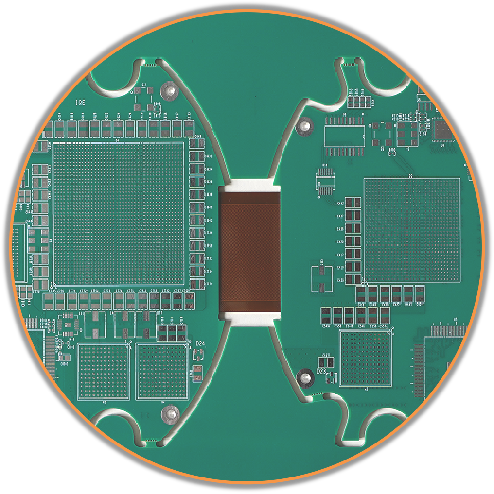
- Multi-layer rigid-flex boards combining standard PCBs with flexible interconnects.
- Flexible sensors and actuators for robotics and prosthetics.
The global flexible printed circuit board market size is estimated to reach nearly $40 billion by 2030 according to analysts. Ongoing innovations in substrate materials, conductive inks, printing processes and 3D structuring will enable even more sophisticated flex circuits to be designed for next-generation electronic devices. The unique benefits of flexible circuits ensure they will continue improving and enhancing electronics across many industries.
Frequently Asked Questions About Flexible Circuit Boards
What are the major differences between rigid and flexible PCBs?
Rigid PCBs use stiff, fiberglass-reinforced substrates while flex circuits use thin, pliable plastic films. Rigid boards provide sturdy structural support for electronics while flex circuits can dynamically bend and move. Flexible boards are thinner, lighter and more resilient to vibrations and frequent flexing.
What types of connectors are used with flexible circuits?
Common connectors for flexible PCBs include zero insertion force (ZIF) connectors, flexible flat cable (FFC) connectors, anisotropic conductive film (ACF), heat seals and crimp/solder connections. Avoid connectors that require high insertion force during dynamic flexing.
How are components attached to flexible circuit boards?
Surface mount components are most commonly attached by soldering to pads along the flex circuit traces. Some components may use conductive adhesive mounting. Larger components can be attached to a rigid section of a rigid-flex board.
How many bend cycles can a flex circuit withstand?
The flex life depends on many factors like substrate material, trace design, and bend radius. Polyimide circuits can endure up to 1 million dynamic flex cycles. Mission-critical aerospace applications may only allow a few thousand guaranteed flex cycles.
Are flexible PCBs more expensive than rigid PCBs?
Yes, flexible PCBs typically have a higher cost per unit area compared to rigid FR-4 boards. But they provide unique benefits like flexibility, thinness and high reliability that justify the added cost for suitable applications. Large production volumes can help reduce flex circuit unit costs.


