


Introduction
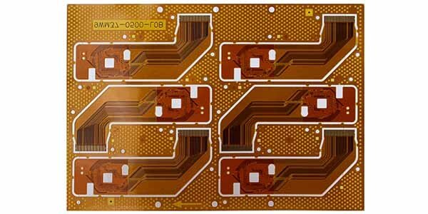
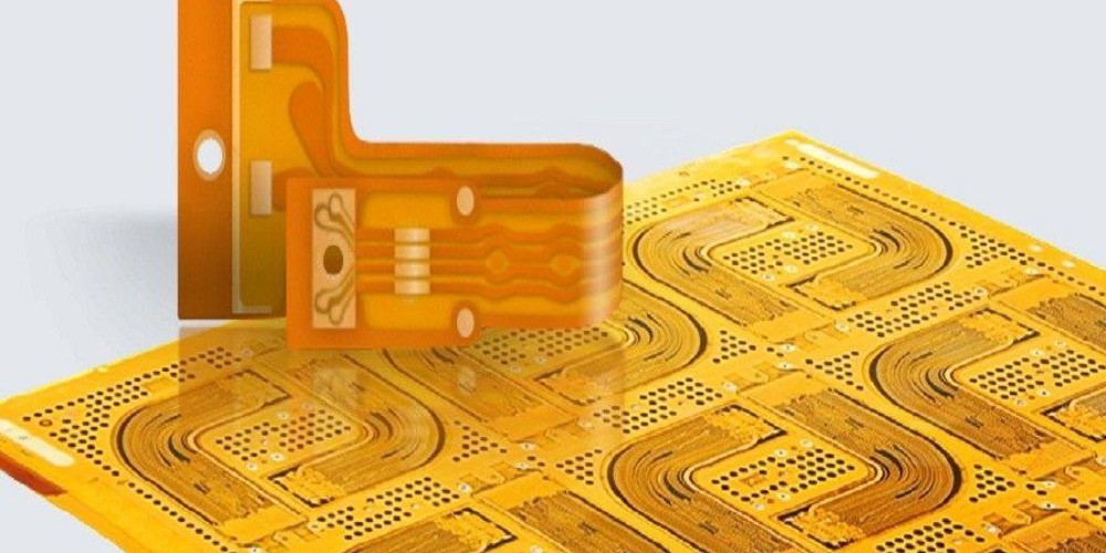
A coverlay flex PCB, also known as a flex circuit or flexible printed circuit board (PCB), refers to a type of PCB that utilizes a flexible insulating substrate material. Unlike rigid PCBs that use rigid FR-4 material, coverlay flex PCBs use a thin, flexible insulator material such as polyimide. This allows the PCB to be bent and flexed during use without damage.
Coverlay flex PCBs provide several advantages over rigid PCBs:
- Can conform to 3D surfaces and move dynamically
- Thinner and lighter weight
- Improved reliability in dynamic applications
- Design flexibility for compact or portable devices
The coverlay is a flexible insulating material laminated over the conductive traces to provide protection and electrical isolation. Common coverlay materials include polyimide, polyester, and liquid crystal polymer (LCP). The coverlay plays a key role in the durability and reliability of the flex PCB.
This comprehensive guide will provide an overview of coverlay flex PCB technology, manufacturing processes, coverlay materials, design considerations, applications, and benefits.
What is a Coverlay Flex PCB?
A coverlay flex PCB consists of three key components:
- Flexible Substrate: Thin insulating base material that provides flexibility. Common materials are polyimide and LCP.
- Conductive Traces: Usually copper traces that are etched or patterned on the substrate to form the circuits.
- Coverlay: Thin insulating coverlayer laminated over the traces for protection and isolation.
Diagram showing components of a coverlay flex PCB (Image source: ResearchGate)
The conductive traces are usually etched copper similar to rigid PCBs. The coverlay material is laminated over the traces to prevent shorts and damage. Vias and component pads are left exposed by laser ablating the coverlay.
Manufacturing Process
Coverlay flex PCBs are manufactured using a subtractive process similar to rigid PCB fabrication:
Step 1: Base Material Prep
The flexible base substrate, usually polyimide, is selected based on the required thickness, dielectric properties, and circuit density. Adhesive is applied to both sides of the base material.
Step 2: Copper Foil Lamination
Copper foil is laminated to both sides of the base material using heat and pressure to form a three-layer sandwich. 1/2 oz and 1 oz copper foils are commonly used.
Step 3: Photolithography
A photoresist layer is applied on the copper layers and imaged using photolithography to define the circuit patterns.
Step 4: Etching
The exposed copper is etched away, leaving only the desired circuit traces protected by the photoresist.
Step 5: Photoresist Strip
The remaining photoresist is stripped away, resulting in the completed circuit traces.
Step 6: Coverlay Lamination
Coverlay material is laser cut to size, aligned over the circuits, and laminated using heat and adhesive.
Step 7: Via Formation
Vias are formed by laser ablation to selectively remove coverlay material over pad areas.
Step 8: Final Testing
Electrical testing and inspection is conducted to verify function.
Coverlay Materials
The coverlay material plays a critical role in the performance and reliability of the flex PCB. The coverlay must exhibit excellent electrical insulation properties, thermal stability, chemical resistance, and mechanical flexibility. Key properties and materials:
Polyimide
- High thermal stability and chemical resistance
- Withstands temperatures up to 400°C
- Popular coverlay choice for high reliability
Polyester
- Lower cost alternative to polyimide
- Moderate thermal and chemical resistance
Liquid Crystal Polymer (LCP)
- Extremely high thermal stability, up to 280°C continuous use
- Low moisture absorption and excellent electrical properties
- Used for highly demanding applications
Flexible Epoxies
- Low cost coverlay option
- Limited thermal and chemical resistance
- Better flexibility than rigid epoxies
Coverlay thickness is typically in the range of 25-100 μm (1-4 mil), with thinner material providing maximum flexibility. Adhesive type can be acrylic, epoxy, or polyimide.
Design Considerations
Designing reliable coverlay flex PCBs requires paying special attention to:
- Bend radius – Avoid tight folds or sharp bends. Maintain minimum bend radius.
- Dynamic flexing – Design for maximum flex cycles. Avoid tearing at fold points.
- Layer stackup – Optimize layer count and stackup. More layers reduce flexability.
- Conductor thickness – Thicker copper is less flexible but handles more current.
- Coverlay openings – Provide adequate spacing around openings to prevent tear propagation.
- Adhesive choice – Acrylic adhesives offer reworkability while epoxy provides maximum bond strength.
Other considerations include thermal management, component selection, cable termination, and testing.
Applications
The unique properties of coverlay flex PCBs make them suitable for many applications:
- Consumer electronics – Cell phones, wearables, VR headsets
- Medical – Imaging equipment, implants, monitors
- Automotive – Sensors, displays, controls
- Aerospace and defense – Avionics, radars, guidances systems
- Industrial – Robotics, instrumentation
- Energy – Solar, wind, oil and gas
For many portable and dynamic applications, coverlay flex PCBs provide the ideal combination of small size, light weight, flexibility, and reliability.
Benefits
Key benefits of coverlay flex PCB technology:
- Flexible – Can conform to 3D shapes and dynamic motion profiles.
- Lightweight – Thin polyimide substrates are lighter than FR-4.
- Reliable – Coverlay protects circuits from wear and tear.
- Compact – Tight bend radii allow dense routing in small products.
- Dynamic – Withstands millions of flex cycles without failure.
- Rugged – Resists shock, vibration, moisture, and chemicals.
- High Speed – Low dielectric loss supports high frequency applications.
By selecting the right materials and design, coverlay flex PCBs deliver optimized performance in demanding applications where rigid PCBs fall short.
Frequently Asked Questions
Here are some common questions regarding coverlay flex PCBs:
Q: What are typical coverlay thicknesses used?
A: Typical coverlay thickness range from 25 μm (1 mil) to 100 μm (4 mil). Thinner coverlay provides maximum flexibility. 25-50 μm is common for consumer electronics, while 50-100 μm is used for more demanding flexing applications.
Q: What coverlay materials can withstand the highest temperatures?
A: Polyimide coverlay materials offer the highest thermal capabilities, withstanding continuous use temperatures over 300°C. Liquid crystal polymer (LCP) coverlay is also highly thermally stable.
Q: How many layers can a flex PCB have?
A: Although 2-4 layers are typical, flex PCBs can have up to 12 layers or more by interleaving flexible dielectric layers with thin copper. However, increasing layer count reduces flexibility and adds cost.
Q: What are recommended minimum bend radii?
A: Typical minimum bend radii range from 2-10 times the total PCB thickness depending on construction. Dynamic flexing requires larger bend radii than static bends. Flex PCB suppliers can provide recommended bend radius.
Q: Can surface mount components be used on flex PCBs?
A: Yes, flex PCB assemblies can utilize SMT components. Adhesives are used to reinforce mechanical joints. Smaller, lighter components are preferred to minimize mass and inertia during flexing.
Conclusion
Coverlay flex PCB technology enables flexible, dynamic, and reliable circuits in applications ranging from consumer gadgets to mission-critical aerospace systems. Careful selection of coverlay and base materials along with robust design can ensure that coverlay flex PCBs survive millions of flex cycles in the harshest operating conditions. With their versatility and durability, coverlay flex PCBs deliver connectivity solutions where rigid circuits simply cannot.