
Part of the rigid-flex circuit board resource.
Define the fixed regions, fold direction, bend locations, assembly order, and service access in the enclosure. Distinguish a flex section that bends only during installation from one that moves repeatedly. State the environmental conditions and any bend-life qualification target. A flat outline cannot communicate those requirements on its own.
Calculate with finished flex thickness
The relevant thickness includes copper, dielectric, adhesive, and coverlay in the bending section. It is not the finished rigid-board thickness and not just the bare polyimide film. Published ratios are construction-specific screening references; the final bend geometry needs approval for the selected material and manufacturing process.
Manage the rigid-to-flex transition
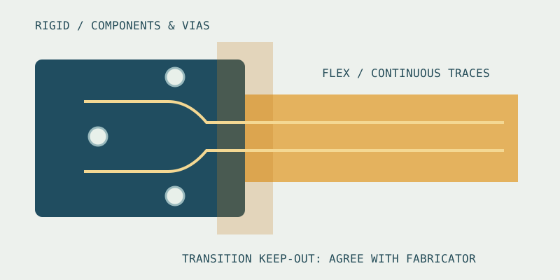
Define transition boundaries on fabrication and assembly drawings. Agree component, pad, via, and stiffener-edge restrictions with the fabricator. Avoid concentrating strain at a rigid edge, coverlay opening, abrupt trace change, or adhesive termination. Do not copy a numeric keep-out from an unrelated stack and label it a universal minimum.
Route for both mechanics and electrical behavior
Use smooth routing through bending areas and avoid unnecessary discontinuities. Review trace orientation and opposing-layer alignment for the selected construction. Decide reference-plane geometry from the signal and mechanical requirements together. Hatched copper changes the electrical reference and must not be substituted solely to make a flex look more compliant.
Define via and pad exceptions explicitly
Move plated features and attachment points away from the active bend where possible. A via that fits inside the board outline may still be mechanically inappropriate. If a constrained design requires an exception, send the geometry and bending duty for a documented review rather than hiding it in a generic design-rule setting.
Release a drawing with acceptance criteria
Identify IPC-2223 and IPC-6013 as applicable design and performance references with a specified revision and class where required. Add regional stackups, finished thicknesses, bend direction, tolerances, test requirements, and approved materials. This checklist does not reproduce or replace the standards.
Next steps for your project
Connect this review with the regional stackup, material choices, and design checklist. Use the design workbench to organize initial parameters, then send the project for a quotation review.