

What are Flex Boards?
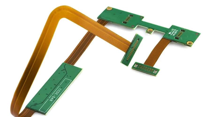
A flex circuit, also known as a flex board or flexible printed circuit board (FPCB), is a type of printed circuit board (PCB) made of flexible insulating material with thin conductive traces on one or both sides. The flexible substrate allows the board to bend and twist to fit into tight spaces and movable parts.
Flex boards provide several advantages over rigid PCBs:
- Flexible and foldable – can fit into tight spaces and movable parts
- Lightweight and thin – takes up less space
- Highly customizable – can be designed into any shape
- Durable and dynamic – can withstand repeated bending
- Efficient routing – traces can make 90° turns
Flex circuits are widely used in compact consumer electronics like mobile phones, laptops, cameras, and wearable devices. They are also found in automotive, aerospace, medical, and industrial applications.
Types of Flex Boards
There are several types of flex boards, classified by the number of conductive layers:
| Flex Board Type | Layers | Description |
|---|---|---|
| Single Sided | 1 | Traces on one side only |
| Double Sided | 2 | Traces on both sides |
| Multilayer | 3+ | Multiple trace layers laminated together |
| Rigid-Flex | – | Combines rigid and flex sections |
Single sided flex boards have conductive traces patterned on one side of the substrate. They provide basic flexibility for simple applications.
Double sided flex boards have traces on both sides, allowing more complex circuitry in a compact form factor. The two sides are electrically connected with plated through holes.
Multilayer flex boards consist of multiple conductive trace layers laminated together, providing the most design flexibility. Signals can cross between layers through plated through holes.
Rigid-flex boards combine rigid FR-4 PCB sections with flexible circuit sections. This allows some portions of the circuitry to remain fixed, while other areas are dynamic.
Flex Board Materials
The flexible material that makes up the substrate of flex boards can vary. Common options include:
- Polyimide (Kapton) – Most popular, high temp resistance
- Polyester (PET) – Lower cost, less heat resistant
- Polyamide – High chemical resistance
- LCP (Liquid Crystal Polymer) – Excellent high frequency performance
The conductor is typically etched copper foil, with thickness ranging from 1 to 3 oz (35 to 105 μm). Some flex boards use annealed copper for improved flex life. The dielectric layer is an acrylic or polyimide adhesive.
Flex Board Design Guidelines
Designing a reliable flex board requires following certain guidelines:
- Bend radius – Avoid tight folds. Maintain at least 2x the board thickness bend radius.
- Layer stackup – Stagger the neutral axis to prevent cracking. Put conductors in the center.
- Conductor width – Keep traces between 0.1-0.3mm. Wider conductors can crack.
- Board thickness – Target between 50-100μm. Thicker boards are less flexible.
- Adhesive choice – Use flexible acrylic or polyimide adhesive. Avoid rigid epoxy.
- Reinforcements – Add stiffeners at connectors or high stress areas.
- Anchor points – Provide secure points for flex board attachments.
- Heat management – Ensure suitable operating temp range for materials used.
Following these guidelines helps create a flex board optimized for dynamic bending applications.
Flex Board Fabrication Process
Fabricating a flex board involves specialized processes, equipment, and materials compared to rigid PCB fabrication. Here is a general overview of the flex board fabrication process:
1. Design
- Create board layout with CAD software like Altium, Eagle, KiCad.
- Design for specified bend radius, conductor spacing, layer stackup.
- Add test points, fiducials, and other features.
2. Photo Plotting
- Laser plot gerber files onto photosensitive film.
- Requires high precision plotters with ~1μm resolution.
3. Imaging
- Laminate photoresist dry film onto copper clad dielectric.
- Expose board through phototool film with UV light.
- Develop photoresist to create patterned etch mask.
4. Etching
- Etch away unwanted copper using chemical etchants.
- Common etchants: ferric chloride, ammonium persulfate.
- Leave desired conductor pattern protected by photoresist.
5. Stripping and Oxidation
- Strip away remaining photoresist mask.
- Dip boards in microetch to remove oxidation.
6. Dielectric Layer Lamination
- Adhere flexible dielectric layers using heat and pressure.
- Build up multilayer board with alternating layers.
- Drill through holes with microvia laser drill.
7. Plating
- Electrolytically plate copper over traces and through holes.
- Plate thin initial seed layer, followed by thicker conductor layer.
8. Solder Mask
- Laminate solder mask layer for insulation and marking.
- Print legend with component locations, markings.
9. Finishing
- Test boards for defects using electrical testing and inspection.
- Route boards from panel into individual PCBs.
- Apply protective coatings as needed.
This covers the basic flex board fabrication process. There are additional steps for more complex designs or HDI processing.
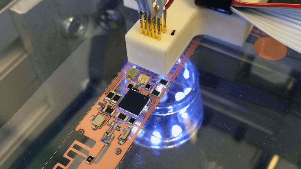
Flex Board Assembly
Assembling components onto flex boards also requires some specialized techniques:
- Adhesives – Epoxies and acrylics are commonly used to mount components.
- SMT – Reflow soldering temperature profiles must match flex board material.
- Plated holes – Leaded components can be wave or hand soldered.
- Stiffeners – Rigid stiffening bars can be added for durability.
- Encapsulation – Conformal coating protects against environmental damage.
- Folding and shaping – Carefully fold and shape board into intended form after assembly.
With careful assembly practices, reliable flex assemblies can be manufactured.
Flex Board Testing
Testing helps ensure flex boards meet requirements under dynamic conditions:
- Visual inspection – Check for physical defects, nicks, cracks.
- Flying probe – Electrically probe test boards for opens, shorts.
- ICT fixture – Use special fixture to electrically test while flexing.
- Continuity testing – Verify conductors have no opens through full range of motion.
- HASS testing – Environmental stress testing of bending, twisting, vibration.
- Impedance testing – Validate matched impedance of high speed signals.
Rigorous testing gives confidence in the reliability of a flex board design.
Flex Board Applications
Due to their small, lightweight, and dynamic nature, flex boards are used in a wide variety of applications:
Consumer Electronics
- Mobile phones – interconnect various sub-assemblies
- Laptops – interconnect motherboard and display
- Digital cameras – flexible interconnections for image sensor
- Wearables – bendable circuits for watches, fitness bands
Automotive
- Circuitry in steering system, doors, headlights, engine
- Replace bulky wire harnesses
- Built-in capabilities like heating, lighting, sensing
Medical
- Implanted devices – pacemakers, sensors, pumps
- Endoscopes and catheters
- Wearable health monitors
Industrial
- Robotics – arms, joints, grippers
- Factory automation – flexible interconnects for sensors and actuators
Aerospace and Military
- Guidance systems
- Engine instrumentation
- Missile firing and control circuits
Flex boards continue finding new applications as technology evolves.
Flex Board vs Rigid Board Tradeoffs
While flex boards provide unique advantages, traditional rigid boards still have their place. Here are some of the tradeoffs:
| Parameter | Flex Boards | Rigid Boards |
|---|---|---|
| Flexibility | Highly flexible and dynamic | Completely rigid |
| Density | Moderate. Conductors have spacing rules | Very high. Tight conductor spacing |
| Layers | Typically 1-6 layers | Up to 30+ layers possible |
| Temperature range | Typically -55°C to 125°C | Can withstand higher temps >150°C |
| Lead time | Longer. Specialized process steps | Shorter. Standardized process |
| Cost | Typically higher. Low volume production | Lower. High volume optimized |
Trends and Innovations in Flex Boards
Some key trends and innovations in flex circuit technology include:
- Extremely thin flex materials down to 12 microns for tight bend radii
- Flex-on-flex technology, embedding thin flex layers within flex board
- New polymer materials like LCP with improved thermal and RF performance
- Chips embedded directly into flex board substrate
- Flexible electronics like OLED displays and printed sensors
- 3D formed flex circuits that take on 3D shapes
- Flex-rigid-flex boards that integrate multiple areas of flexibility
As electronics grow more compact and lightweight, flex circuitry will continue advancing to meet the need.
Conclusion
Flex boards provide a unique set of advantages with their thin, lightweight, bendable form factor. From consumer gadgets to mission-critical systems, flex circuits enable electronics to go places rigid boards simply can’t. With careful design and manufacturing processes, flex boards provide reliability under dynamic operating conditions. As technology trends require ever-smaller and more flexible electronics, flex boards will continue growing as an enabling interconnect solution.
Frequently Asked Questions
What are some typical flex board thickness values?
Typical flex board thickness ranges from about 25 microns up to around 150 microns. Very thin flex boards can be 12 microns for tight bend radius applications. Thicknesses above 150 microns start to impact flexibility.
How many times can a flex board be dynamically flexed?
Properly designed flex boards can withstand hundreds of thousands of dynamic flex cycles. Factors like bend radius, materials, layer stackup, and reinforcement impact flex life ratings.
What line/space rules are common for flex board conductors?
For outer layer conductors, 5/5 mil (0.127mm) line/space is common. High density designs may go down to 3/3 mil spacing. Anything below 2 mil can risk reduced reliability.
What are stiffeners and what are they used for?
Stiffeners are thick rigid bars adhered to high stress areas of a flex board to provide mechanical support. They are often used at connectors or along edges prone to wear. Stiffeners prevent cracking while allowing flexibility elsewhere.
How are components attached to flex boards?
SMT components can be reflow soldered. Leaded components use soldered plated through holes. Adhesives like epoxy or acrylic are commonly used to attach larger components. Stake pins can also mechanically fasten parts.