

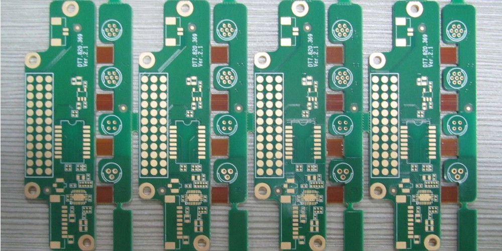
What is a Rigid PCB?
A rigid printed circuit board (PCB) is the most common type of PCB. It consists of an insulating substrate made up of materials like FR-4 (fiberglass reinforced epoxy), polyimide, Arlon, Rogers, etc. The substrate has conductive copper traces etched on top and bottom that are used to connect various components. Rigid PCBs provide mechanical support and electrical connectivity for electronic components that are soldered to the board.
Rigid PCBs are widely used in all types of electronic devices including computers, mobile phones, automotive electronics, industrial automation systems, medical equipment, aerospace systems, and more. Compared to flexible PCBs, rigid PCBs offer:
- Excellent mechanical stability and durability
- Ease of assembly for components
- Ability to withstand high temperatures
- Good electrical performance at high frequencies
Advantages of Rigid PCBs
Here are some of the main advantages of using rigid PCBs:
Structural Integrity
The rigid and non-flexible structure of the PCB substrate offers a sturdy foundation for mounting and securing electronic components. Rigid PCBs don’t bend or flex easily, preventing issues with traces cracking or components coming loose over time.
Ease of Assembly
Components can be easily soldered and assembled onto rigid PCBs using automated PCB assembly equipment. Rigid boards can also accommodate through-hole and surface mount components.
Thermal Performance
The insulating substrate and copper layers enable efficient heat dissipation in rigid PCBs. This allows them to withstand high temperature environments and operate at higher power levels.
Miniaturization
Rigid PCBs allow for greater miniaturization and density of electronic circuitry. More components and connections can fit onto a small rigid PCB.
High Frequency Operation
The dielectric materials used in rigid PCBs like FR-4 allow them to perform well at high frequencies like radio frequencies and microwave frequencies. They have good high frequency insulation properties.
Cost Effectiveness
Rigid PCB fabrication methods are standardized and optimized. This makes rigid PCBs a very cost-effective solution for many electronic devices.
Rigid PCB Materials
Rigid PCB substrates are made using a variety of materials. Some common rigid PCB materials include:
FR-4
FR-4 glass epoxy is the most commonly used low-cost rigid PCB material. It consists of woven fiberglass cloth bonded with an epoxy resin binder. FR-4 has good mechanical strength and excellent electrical insulating properties.
High Frequency PCB Materials
For high frequency applications, rigid PCB materials like Rogers and Arlon offer superior RF performance compared to FR-4. But they are also more expensive.
Aluminum
Aluminum PCBs have a base metal of aluminum instead of FR-4. They have good thermal conductivity for heat dissipation. But they are also electrically conductive and need isolation layers.
Polyimide
Rigid polyimide boards can withstand very high temperatures over 300°C. This makes them useful for automotive and aerospace applications. But they are expensive.
CEM-1, CEM-3
CEM-1 and CEM-3 are inexpensive PCB materials with properties closer to FR-4. They have low moisture absorption.
PTFE
PTFE (Teflon) rigid boards have excellent electrical insulating properties. They are durable and withstand high temperatures. But they are also expensive.
Rigid PCB Fabrication
Rigid PCBs are fabricated using the following typical sequence of steps:
- Design – The PCB layout is designed in CAD software like Altium, Eagle, KiCAD, etc.
- Prototyping – Prototype PCBs are produced in small volumes for testing.
- Fabrication – The fabrication process consists of:a) Laminating copper-clad insulating substrateb) Imaging/Photoresist coatingc) Exposure and developingd) Etching to form tracese) Stripping photoresistf) Drilling holesg) Plating and coating
- Assembly – Electronic components are soldered to form a functional PCB assembly.
- Testing – The fabricated PCB is tested for defects and functionality.
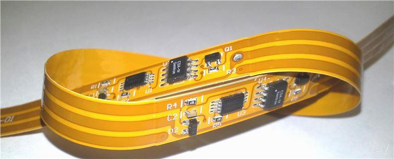
Rigid Flex PCBs
Rigid-flex PCBs consist of rigid sections combined with flexible sections. This allows the PCB to adapt to different shapes while still providing stability and robustness. The rigid portions typically contain the bulk of the electronic components. The flexible portions connect the rigid sections and allow the PCB to bend and fold in certain areas.
Rigid-flex PCBs offer benefits like:
- Dynamic flexing and three-dimensional design
- Reduction in connectors and wires
- Increased reliability
- Miniaturization
- Improved high frequency performance
They are more complex and expensive to manufacture compared to simple rigid PCBs. Rigid-flex PCBs are useful for applications like laptops, mobile devices, aerospace systems, industrial cameras, etc.
Factors to Consider When Choosing a Rigid PCB
Here are some key considerations when selecting a rigid PCB:
- Frequency – The dielectric material determines the PCB’s high frequency performance. FR-4 is sufficient up to a few GHz while ceramic-filled PTFE boards can reach 50+ GHz.
- Thermal – High power boards may require metal core PCBs or added thickness for heat dissipation. The coefficient of thermal expansion of the PCB material also matters.
- Lead-free – Most PCB assembly uses lead-free soldering now, so the PCB material must withstand lead-free soldering temperatures around 260°C.
- Flexible sections – If flexible sections are needed, a rigid-flex PCB should be used instead of a simple rigid PCB.
- Board thickness – Thicker boards are stronger and support heavier components while thinner boards allow more compact designs.
- High speed design – Controlled impedance traces, stack ups, and precise dielectric constants are needed for high speed signal integrity.
- Environment – If the PCB will be used in extreme conditions like high humidity, high temperature, etc. specialized materials are required.
| PCB Material | Dielectric Constant | Loss Tangent | Frequency Range |
|---|---|---|---|
| FR-4 | 4.5 | 0.02 | Up to 5 GHz |
| Rogers RO4003C | 3.38 | 0.0027 | Up to 10+ GHz |
| Polyimide | 3.4 | 0.004 | Up to 2 GHz |
| PTFE | 2.1 | 0.001 | Up to 50+ GHz |
PCB Design and Simulation
To create a rigid PCB, the circuit schematic is first designed in CAD software. This schematic is then converted into a physical PCB layout depicting exact component locations and routing of copper traces to interconnect them on the board layers.
PCB layout involves carefully optimizing the placement and routing to achieve:
- Compact design
- EMI/noise reduction
- Controlled impedance for high speed signals
- Heat dissipation performance
- Easy manufacturability and assembly
Simulation can be used to model the electrical, thermal, and mechanical performance of the PCB design before fabrication. Common analyses like signal integrity, power integrity, thermal simulation, and vibration/shock simulations can be performed. This helps validate and optimize the PCB design.
Applications of Rigid PCBs
Rigid PCBs are ubiquitous in all electronics sectors. Some examples of applications include:
- Computers – Motherboards, graphics cards, etc.
- Consumer Electronics – Smartphones, TVs, game consoles, etc.
- Automotive – Engine control units, infotainment systems, etc.
- Aerospace – Avionics, guidance systems, etc.
- Medical – Diagnostic equipment, surgical tools, implants, etc.
- IoT Devices – Smart home products, wearables, sensors, etc.
- Military – Radar, communications, guidance systems etc.
- Industrial – Programmable logic controllers, robotics, control systems etc.
Almost every electronic device relies on rigid PCBs to structurally support and interconnect its components. Their excellent manufacturability and cost-effectiveness make rigid PCBs ideal for commercial and industrial electronics.
Future Outlook on Rigid PCBs
Rigid PCB technology will continue advancing in line with the electronics industry. Some trends influencing rigid PCB development are:
- Continued miniaturization to pack more functionality into compact devices. This leads to greater PCB densities with smaller traces/spaces and high layer counts.
- More high speed digital and mixed signal designs requiring excellent signal integrity. This demands improved impedance control and modeling.
- Higher operating frequencies into the mmWave region for 5G, satcom, radar, etc. This requires novel PCB materials with lower losses.
- Growth of higher power electronics like traction inverters for EVs. Reliable thermal management is crucial for these applications.
- Embedding of passives and actives within the PCB to further miniaturize designs.
- Expanding applications of rigid-flex PCBs offering mechanical flexibility combined with rigid support for components.
- Improvements in automated optical inspection and testing to enhance PCB quality and yields.
- Environment-friendly ‘green’ PCB materials and processes.
Rigid PCBs will continue to evolve incrementally to suit the ever-advancing demands of the electronics industry with regards to speed, power, functionality, quality, and cost.
Frequently Asked Questions
Q1. What are the different types of rigid PCB materials?
Some common rigid PCB substrate materials include FR-4 glass epoxy, Rogers, Arlon, polyimide, aluminum, CEM-1/CEM-3, PTFE/Teflon, etc. Each material has different properties suited for different applications and requirements.
Q2. How are holes and vias formed in rigid PCBs?
Holes and vias are mechanically drilled into the rigid PCB substrate. These holes are then plated with copper to form an electrical connection between layers. Microvias under 0.15mm size may be formed by laser drilling.
Q3. What are HDI PCBs?
HDI or high density interconnect rigid PCBs have trace/space less than 100 microns. They allow greater component density and multi-layer stacking over 16 layers. HDI PCBs often use microvias for interconnection.
Q4. What is the difference between single-sided, double-sided, and multilayer rigid PCBs?
Single-sided have copper traces on one side, double-sided have traces on both sides, while multilayer have 3 or more layers of copper interconnects buried internally within the PCB.
Q5. Can rigid PCBs contain embedded components?
Yes, rigid PCBs are increasingly incorporating embedded passive components like resistors/capacitors and even embedded actives like ICs within the board substrate. This offers further miniaturization.