

Introduction to Fr4 Semiflex
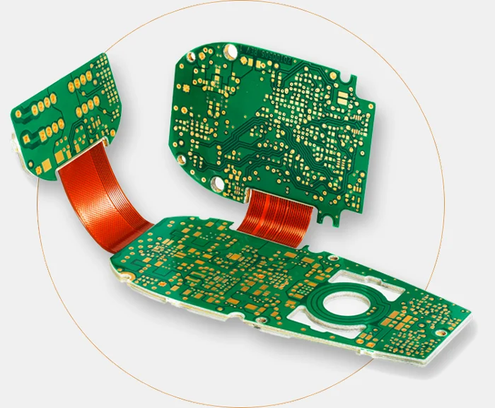
Fr4 semiflex is a flexible printed circuit board (PCB) material that combines the performance of standard FR4 rigid PCBs with the flexibility of polyimide flex circuits. Semiflex PCBs provide several advantages over traditional rigid or flexible PCB materials:
- High temperature performance – Fr4 semiflex can withstand soldering temperatures up to 280°C, similar to rigid FR4 PCBs. This allows lead-free soldering processes.
- Excellent electrical properties – The FR4 resin system provides low loss, high insulation resistance, and stable electrical performance.
- Design flexibility – Semiflex PCBs can be bent and flexed to fit into tight spaces and movable assemblies. They are ideal for dynamic flexing applications.
- Reliability – The FR4 base prevents flex cracks that can occur in polyimide flex circuits after repeated bending. This improves reliability in dynamic applications.
- Easy assembly – Components can be soldered onto semiflex PCBs using standard FR4 assembly processes. No special flex circuit assembly is required.
- Cost-effectiveness – Semiflex provides performance advantages over flex circuits at a lower cost.
With these benefits, fr4 semiflex PCBs are being widely adopted for flexible circuit designs in consumer electronics, automotive electronics, industrial controls, and medical devices.
Properties of Fr4 Semiflex Material
Fr4 semiflex combines an FR4 substrate with a bonded copper foil that allows flexible bending and folding of the PCB. The key properties that make this material suitable for high performance flex PCBs are:
Dielectric Properties
- Dielectric constant (Dk): 4.4-4.6
- Dissipation factor (Df): 0.02
- Dielectric strength: >1500 V/mil
The FR4 resin system provides consistent, low-loss dielectric performance, with dielectric constant and loss values similar to standard FR4 materials.
Physical Properties
- Flexible thickness: 25-100 μm
- Bend radius: 10x thickness or higher
- Glass transition temperature (Tg): >140°C
- Decomposition temperature: 340°C
Semiflex PCBs can be supplied in thinner flexible thicknesses while maintaining the high Tg and thermal performance of FR4. Recommended bend radius is 10 times the material thickness.
Electrical Properties
- Volume resistivity: 1 x 10<sup>15</sup> ohm-cm
- Surface resistivity: 1 x 10<sup>13</sup> ohms
- Breakdown voltage: >1500 VAC
- Flammability: UL 94 V-0
The electrical resistance properties allow semiflex PCBs to insulate and perform reliably at high voltages. The flammability rating is V-0 per UL 94 standards.
Copper Foil
- Foil type: Rolled annealed copper
- Foil thickness: 12-35 μm
- Peel strength: >4 lbs/in
Copper foils specially bonded to the FR4 substrate provide the flexibility as well as strong adhesion to survive dynamic bending.
Applications of Fr4 Semiflex Circuits
Some of the common application areas where fr4 semiflex PCB technology provides advantages are:
Consumer Electronics
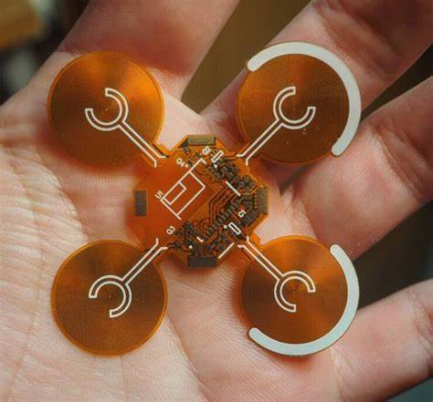
- Wearable devices
- Portable medical devices
- Mobile phones
- Laptops
Semiflex allows small, lightweight, and durable flexible PCBs to be designed for wearable and portable consumer gadgets.
Automotive Electronics
- Automotive sensors
- Infotainment control panels
- ADAS assemblies
In cars, semiflex PCBs withstand under-hood temperatures for automotive sensors, while providing flexing capability for movable assemblies like control panels and camera modules.
Industrial Electronics
- Robotics
- Machine controls
- IoT edge nodes
For industrial automation and control, semiflex delivers reliability, temperature resistance, and flexibility suited for robots, control systems, and remote IOT devices.
Medical Equipment
- Patient monitoring systems
- Diagnostic devices
- Surgical equipment
In medical uses, semiflex provides a clean, sterilizable, and reliable interconnect solution for patient-connected devices like monitors, probes, and surgical hand pieces.
Here is a comparison of semiflex PCB attributes for some common application requirements:
| Application | Key Requirements | Semiflex Benefits |
|---|---|---|
| Wearable Device | Small size<br>Flexibility<br>Durability | Thin profile<br>Dynamic flexing<br>Flex crack resistance |
| Automotive Sensor | High temp performance<br>Vibration resistance | 280°C soldering<br>FR4 stability |
| Industrial Control | Reliable operation<br>Compact form factor | Long flex life<br>Tight bend radii |
| Medical Equipment | Sterilizability<br>Bio-compatibility | Clean FR4 material<br>No outgassing |
This table summarizes how the semiflex design attributes meet the critical needs of different use cases. The combination of FR4 performance and flexible circuit reliability makes it suitable for demanding dynamic flex applications across industries.
Design and Manufacturing Process
While semiflex PCBs offer advantages, the design and manufacturing process requires some unique considerations compared to rigid boards.
Layout Recommendations
- Use large bend radii – 10x material thickness is ideal
- Avoid sharp corners at bend points
- Place components in neutral bend areas when possible
- Do not locate vias at high stress bending zones
- Reduce connector pin density in bend areas
- Allow clearance for components on flexible area
Careful layout is needed to prevent excessive stresses in bending regions. High-stress points require design relief features.
Fabrication Process
- Starts with an FR4 panel
- Copper foils are laminated on one or both sides
- Photolithographic patterning forms the cu traces
- Laser cutting/CNC milling used for intricate board shapes
- Etching and plating steps similar to rigid PCBs
- Final contours cut prior to bending and assembly
Semiflex boards utilize many of the same fabrication processes as rigid FR4 PCBs. The additional lamination and contour cutting steps produce the flexible circuit regions.
Assembly Notes
- Parts are soldered using standard SMT assembly
- Adhesives attach components in flexible areas
- Avoid placing large, heavy parts in flexing zones
- Provide strain relief to cables, connectors
- Test flex capability before final enclosure
Component placement requires planning to prevent shorts or openings during dynamic bending. Strain relief for external connections is critical.
Prototyping and evaluating semiflex designs early with an experienced manufacturer is recommended to ensure manufacturability and reliability goals are achieved.
Fr4 Semiflex vs. Polyimide Flex Circuits
Polyimide film is another common flexible circuit material. Here is a comparison between semiflex and polyimide flex:
| Parameter | Semiflex | Polyimide Flex |
|---|---|---|
| Dielectric Material | FR4 epoxy resin | Polyimide polymer |
| Flexible Thickness Range | 25-100 μm | 12-125 μm |
| Minimum Bend Radius | 10x thickness | 10x thickness |
| Soldering Temperature | 280°C (lead-free) | 245°C |
| Dielectric Constant | 4.4-4.6 | 3.4-3.5 |
| Thermal Expansion | X: 13 ppm/°C<br>Y: 45 ppm/°C | X: 20-30 ppm/°C |
| UL Flammability Rating | 94 V-0 | 94 VTM-0 |
| Cost | Low | Medium |
Polyimide has somewhat better flexibility and a lower dielectric constant. But semiflex offers higher temperature operation, better electrical performance, lower cost, and availability from standard PCB manufacturers. The FR4 base also improves flex life and prevents embrittlement over polyimide films.
Trends and Developments
Some of the recent developments to improve semiflex PCB performance and capabilities are:
- Finer trace widths – Semiflex circuits with 8-10 mil traces are becoming standard, allowing higher density designs.
- Embedded passives – Burying capacitors and resistors within the PCB layers saves space and improves electrical performance.
- HDI technology – Laser vias, thinner dielectrics, and stacked microvias provide integration similar to rigid HDI PCBs.
- Improved modeling – FEA simulation tools better predict stresses and optimize layouts for dynamic bending conditions.
- Multi-layer flex – Adding more copper layers accommodates complex flexible circuit designs.
These process enhancements make semiflex a solution for more miniaturized and higher speed flexible circuit applications.
FQA About Fr4 Semiflex
Here are answers to some frequently asked questions about FR4 semiflex PCB technology:
What are some good applications for semiflex boards?
Semiflex is ideal for dynamic flexing circuits like wearable devices, robotic arms, folding display screens, and automotive camera modules. It suits applications needing FR4 performance plus flexible capability.
What are the main advantages of semiflex over polyimide flex?
Semiflex offers higher temperature operation, superior electrical performance, lower cost, and better flex life than polyimide. The FR4 base prevents embrittlement and cracking over repeated flex cycles.
Can components be mounted directly onto the flexible area?
Yes, but parts should be small, lightweight, and specially secured. Adhesives are required to attach components onto the flexible zones. Careful strain relief design is essential.
What are the limitations of semiflex PCB technology?
Minimum bend radius is restricted to about 10 times the material thickness. High density interconnects are challenging in flexible areas due to trace stresses. Polyimide flex circuits are better suited for tight folding applications.
How is impedance controlled in semiflex PCBs?
Trace geometries and dielectric thickness allow impedance tuning similar to rigid boards. Embedded capacitance layers can also be incorporated to provide capacitive decoupling for active semiflex designs.