


What are Quick Turn Flex Circuits?
A quick turn flex circuit, also known as a flex PCB or flexible printed circuit board, is a type of printed circuit board that is flexible and bendable. Quick turn refers to the fast production time, allowing flex circuits to be manufactured and shipped in just a few days compared to weeks for traditional rigid PCBs.
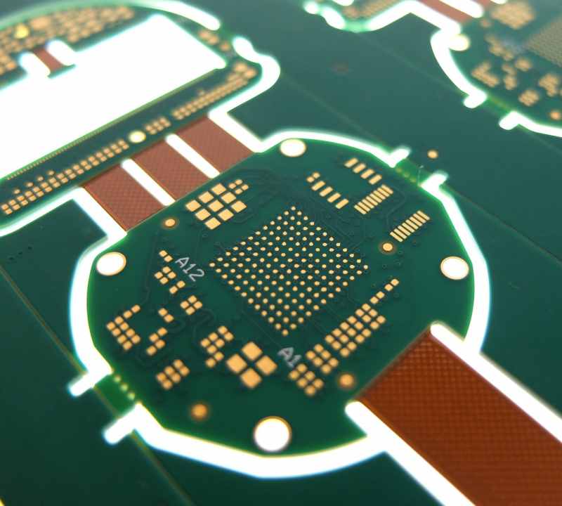
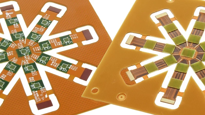
Flex circuits consist of conductive traces and pads laminated onto a thin, flexible dielectric substrate material such as polyimide. The circuits can be bent and twisted to fit into tight spaces and movable assemblies. Quick turn capabilities make flex circuits ideal for prototyping and low volume production.
Benefits of Quick Turn Flex Circuits
- Fast turnaround time – circuits can be produced in just 2-4 days
- Flexible and bendable – can fit into tight spaces and movable assemblies
- Lightweight – thinner than rigid circuit boards
- Scalable manufacturing – low volume to high volume production
- Reliable connections – flexing does not damage the circuitry
- Design freedom – circuits can be shaped and folded to specification
- Single or double sided – circuits can be designed with traces on one or both sides
Applications of Quick Turn Flex Circuits
- Consumer electronics – cameras, music players, mobile devices
- Automotive – sensors, control panels, LED lighting
- Medical – hearing aids, wearables, imaging equipment
- Industrial – robotics, testing and measurement equipment
- Aerospace and defense – avionics, missile guidance systems
Flex circuits are useful anywhere that lightweight, dynamic, and compact PCB solutions are required. The quick turn capabilities make them suitable for rapid prototyping and new product development.
How to Design Quick Turn Flex Circuits
Designing a successful flex circuit requires paying attention to the specialized construction and processes involved. Here are some best practices for flex circuit design:
- Allow for flexing – Include bend areas and relieve stresses with rounded corners and teardrops
- Minimize rigid sections – Only use stiffeners and covers when absolutely required
- Dynamic fold lines – Fold lines will change position during flexing, account for shifting
- Manage layer stackup – Stagger overlapping components, watch adhesive thickness
- Mind trace widths and spacing – Account for flexibility requirements
- Plan component placement – Ensure parts can handle flexing, prevent stubs
- Specify flex-friendly components – Use chip-on-flex, reverse wire bonding
- Minimize vias – Use buried and blind vias instead of through hole
- Watch spacing at edges – Prevent traces and pads from peeling
- Account for thermal expansion – Allow room for expansion and contraction
- Test designs dynamically – Validate that circuits function while flexing
Following flex circuit design guidelines will ensure the circuitry remains reliable despite continuous bending and shaping.
Manufacturing Process for Quick Turn Flex Circuits
Producing a flex circuit is a multi-stage process consisting of specialized fabrication techniques:
1. Design and Layout
The circuit design is created and routed just like a rigid PCB. Design rules must follow flex circuit guidelines.
2. Material Selection
Common flex circuit substrates include polyimide, polyester, PEEK, and fluoropolymers. Thickness ranges from 12.5 to 100 microns. Adhesives are selected.
3. Imaging and Etching
Photolithographic processes transfer the circuit layout onto the copper foil. Etching removes unwanted copper.
4. Die Cutting
A steel rule or laser cutter shapes the raw flex material panels into individual circuits.
5. Lamination
Layers of substrate, adhesive, and copper foil are stacked and laminated under heat and pressure.
6. Plating and Coating
Exposed metal traces are plated and coated to protect against oxidation and improve solderability.
7. Component Assembly
SMT components are placed on the circuitry using solder paste and reflow soldering techniques.
8. Testing and Inspection
Each circuit is tested for functionality. Automated optical inspection checks quality.
9. Shipping
Finished circuits are shipped to the customer. Rapid turnaround keeps lead times short.
The combination of skilled engineering and specialized manufacturing equipment allows quality flex circuits to be delivered in just days.
Choosing a Quick Turn Flex Circuit Manufacturer
Selecting the right flex circuit company is key to achieving short lead times and quality results:
- Ask about turnaround time – Confirm they can deliver in 2-4 days
- Evaluate capabilities – Assess their design, fabrication, and assembly services
- Review materials and processes – Ensure they work with a wide range of flex materials
- Ask for references – Talk to past clients about service and quality
- Check certifications – Look for ISO and industry specific certifications
- Review quality control – Ensure they inspect circuits at multiple stages
- Evaluate supply chain – Choose a vendor with solid material sourcing
- Assess engineering support – Pick a company that provides design assistance
- Check location – A domestic manufacturer avoids shipping delays
- Compare costs – Get quotes from multiple vendors
Choosing a flex circuit company with proven quick turn capabilities and rigorous quality control will get your project delivered on time.
Key Quick Turn Flex Circuit Manufacturers
Some of the top companies specializing in fast turnaround flex PCBs include:
- Flexible Circuit Technologies
- Flexible Interconnect
- All Flex
- Minnesota Wire
- Flexible Circuit Solutions
- Lenthor Engineering
- Quad Industries
Cost Factors for Quick Turn Flex Circuits
The costs of producing a flex circuit can vary substantially depending on:
- Size – Smaller circuits cost less than larger boards
- Layers – Each additional conductive layer adds expense
- Quantity – Prices are higher for prototypes versus production runs
- Special processes – Additional steps like via holes, coatings and more add cost
- Materials – Thicker flexible substrates or high performance materials increase costs
- Components – More complex parts, smaller sizes, and higher quantities add cost
- Testing – Extensive functionality and quality testing increases price
- Delivery time – Faster turnaround times increase costs
- Certifications – Flex circuits for regulated industries require certifications
- Location – Manufacturing in North America typically costs more than Asia
To get accurate pricing, contact manufacturers early in the design phase to discuss your specific project requirements. Most will provide free quotes for flex circuit production.
Design Tips for Affordable Quick Turn Flex Circuits
There are also design decisions that can help reduce flex circuit costs:
- Minimize the number of layers
- Use common flexible substrate materials like polyimide
- Reduce board size as much as possible
- Design with larger features and spacing when possible
- Minimize the number of folded sections
- Use traditional SMT components instead of chip-on-flex
- Standardize designs across product variations
- Build a little extra time into schedules to use economy turnaround times
- Adjust design to panelize circuits efficiently
- Work with manufacturers early in the process to optimize
While quick turn capabilities often justify the premium price, following design and manufacturing best practices can help keep flex circuit costs affordable.
The Future of Quick Turn Flex Circuits
Several technology trends are shaping the future of rapid flex PCB production:
- Improved materials – New flexible substrates are stronger, thinner, and more heat resistant
- Additive manufacturing – Printed electronics methods eliminate etching and simplify processes
- Advanced testing – Automated optical inspection and electrical testing shorten quality control
- Design software – Tools model flex circuit dynamics and improve first-time-right designs
- Supply chain advancements – Software integration and inventory management reduces material lead times
- Higher densities – Finer lines, spaces, and via diameters enable complex flex circuits
- Growth of wearables – Flex circuits support expanding consumer and medical wearable devices
- Foldable devices – Foldable phones, displays, and devices drive flex circuit innovation
- Internet of Things – Flexible interconnects support smarter devices and sensors
Continued improvements across the flex circuit supply chain will enable even faster delivery times, higher complexity, and lower costs.
Frequently Asked Questions about Quick Turn Flex Circuits
Q: How fast can you get quick turn flex circuits?
A: The fastest turnaround times for prototypes are typically 2-4 days. Very simple designs may ship in 1 day. Smaller production runs can ship in 5-7 days.
Q: What types of file formats do flex circuit manufacturers accept?
A: Gerber and DXF files are standard for flex PCB fabrication. Many also accept PDF, PNG, STEP, and 3D models. Always check with the manufacturer.
Q: Can you make revisions to an existing flex circuit design?
A: Yes, revisions can be made easily since photolithographic processes are used. Changes just mean modifying the circuit layout files. New images are generated.
Q: What are the minimum trace widths and spacings for flex circuits?
A: Trace widths can be as small as 0.05 mm (0.002″) and spacing around 0.075 mm (0.003″). This depends on circuit thickness and bending requirements.
Q: How many times can a flex circuit be flexed before failing?
A: Properly designed circuits last for millions of dynamic flex cycles. Fatigue life depends on materials, construction methodology, and radius of folds.
Q: Can components be mounted on both sides of a flex circuit?
A: Yes, components can be placed on one or both sides. Double sided flex circuits allow for higher component densities.
Q: What types of connectors work well with flex circuits?
A: Common connectors include ZIF, FFC, FPC, PCB terminals, soldered wires or pins, and conductive adhesives or tapes.
Q: Can flex circuits be prototyped using 3D printing?
A: Yes, various methods exist for flex circuit 3D printing including aerosol, dispenser, inkjet, and other additive processes. Feature sizes are limited.
Q: What is the typical warranty for quick turn flex circuits?
A: Most manufacturers provide a minimum 6 month to 1 year warranty on flex circuits if they are produced according to supplied specifications.