Introduction to RF Immunity in Audio Amplifiers
Audio amplifiers are susceptible to radio frequency (RF) interference, which can degrade their performance and introduce unwanted noise into the audio signal. RF interference can come from a variety of sources, including nearby radio transmitters, mobile phones, and even the amplifier’s own power supply. To achieve optimal performance and minimize the impact of RF interference, careful PCB Layout techniques must be employed.
In this article, we will explore the various PCB layout techniques that can be used to achieve RF immunity for audio amplifiers. We will discuss the importance of proper grounding, shielding, and component placement, as well as the use of filters and other circuit design techniques. By following these guidelines, designers can create audio amplifiers that are resistant to RF interference and deliver high-quality audio performance.
The Impact of RF Interference on Audio Amplifiers
RF interference can have a significant impact on the performance of audio amplifiers. When an amplifier is exposed to RF energy, it can rectify the RF signal and introduce unwanted noise into the audio signal. This noise can manifest as a high-pitched whine, buzzing, or other distortion that can be heard through the speakers or headphones.
The severity of the RF interference depends on several factors, including the strength of the RF signal, the frequency of the signal, and the sensitivity of the amplifier. In some cases, the interference may be barely noticeable, while in others it can completely overwhelm the audio signal.
To minimize the impact of RF interference, designers must take steps to shield the amplifier from external RF sources and to prevent the amplifier from generating its own RF noise. This can be achieved through proper PCB layout techniques, as well as through the use of filters and other circuit design techniques.
Grounding Techniques for RF Immunity
One of the most important aspects of achieving RF immunity in audio amplifiers is proper grounding. A well-designed grounding scheme can help to minimize the impact of RF interference by providing a low-impedance path for RF currents to flow away from sensitive Circuit Components.
Star Grounding
One common grounding technique is known as “star grounding.” In this approach, all ground connections are made to a single point, known as the “star point.” This helps to minimize the potential for ground loops and other sources of noise.
To implement star grounding, designers should create a separate ground plane for each section of the circuit, such as the power supply, input stage, and output stage. Each ground plane should be connected to the star point through a low-impedance path, such as a wide trace or a copper pour.
Ground Planes
Another important grounding technique is the use of ground planes. A ground plane is a large area of copper that is used to provide a low-impedance path for ground currents. Ground planes help to minimize the potential for ground loops and other sources of noise, and they also provide a shield against external RF interference.
When designing a ground plane, it is important to keep the plane as continuous as possible. Any gaps or slots in the plane can create high-impedance paths for ground currents, which can lead to increased noise and reduced RF immunity.
Component Placement
Proper component placement is also critical for achieving RF immunity in audio amplifiers. Components should be placed as close as possible to their associated ground plane, and any components that are sensitive to RF interference should be shielded or located away from potential sources of interference.
One common technique for minimizing the impact of RF interference is to use shielded enclosures for sensitive components, such as input stages and power supplies. These enclosures can be made from metal or other conductive materials, and they help to block external RF energy from reaching the sensitive components.

Shielding Techniques for RF Immunity
In addition to proper grounding, shielding is another important technique for achieving RF immunity in audio amplifiers. Shielding involves the use of conductive materials to block or absorb external RF energy, preventing it from reaching sensitive circuit components.
Shielded Cables
One common shielding technique is the use of shielded cables for input and output connections. Shielded cables have a conductive outer layer that surrounds the signal conductors, helping to block external RF energy from reaching the sensitive components inside the cable.
When using shielded cables, it is important to ensure that the shield is properly grounded at both ends of the cable. If the shield is not properly grounded, it can act as an antenna and actually increase the amount of RF interference that reaches the amplifier.
Shielded Enclosures
As mentioned earlier, shielded enclosures can also be used to protect sensitive components from external RF interference. These enclosures can be made from metal or other conductive materials, and they help to block RF energy from reaching the components inside.
When designing a shielded enclosure, it is important to ensure that there are no gaps or openings that could allow RF energy to leak in. Any openings should be kept as small as possible, and they should be covered with conductive gaskets or other materials to ensure a tight seal.
Ferrite Beads
Ferrite beads are another useful tool for achieving RF immunity in audio amplifiers. Ferrite beads are small, cylindrical devices that are made from a magnetic material. When placed in series with a signal or power line, they act as a high-impedance barrier to RF energy, helping to prevent it from reaching sensitive circuit components.
Ferrite beads are particularly useful for filtering out high-frequency noise from power supply lines. By placing a ferrite bead in series with the power supply line, designers can help to minimize the amount of RF energy that reaches the amplifier, improving its overall RF immunity.
Circuit Design Techniques for RF Immunity
In addition to proper PCB layout and shielding techniques, there are several circuit design techniques that can be used to achieve RF immunity in audio amplifiers. These techniques involve the use of filters, decoupling capacitors, and other components to minimize the impact of RF interference.
LC Filters
LC filters are a common type of filter used in audio amplifiers to minimize the impact of RF interference. An LC filter consists of an inductor (L) and a capacitor (C) connected in series or parallel. The inductor and capacitor form a resonant circuit that helps to block or attenuate RF energy at a specific frequency.
LC filters are particularly useful for filtering out high-frequency noise from input and output signals. By placing an LC filter at the input or output of the amplifier, designers can help to minimize the amount of RF interference that reaches the sensitive circuit components.
RC Filters
RC filters are another type of filter that can be used to achieve RF immunity in audio amplifiers. An RC filter consists of a resistor (R) and a capacitor (C) connected in series or parallel. The resistor and capacitor form a low-pass filter that helps to block or attenuate high-frequency noise.
RC filters are particularly useful for filtering out high-frequency noise from power supply lines. By placing an RC filter at the power supply input of the amplifier, designers can help to minimize the amount of RF energy that reaches the sensitive circuit components.
Decoupling Capacitors
Decoupling capacitors are another important component for achieving RF immunity in audio amplifiers. A decoupling capacitor is a capacitor that is placed between the power supply and ground, helping to filter out high-frequency noise and prevent it from reaching sensitive circuit components.
Decoupling capacitors are typically placed as close as possible to the power supply pins of sensitive components, such as op-amps and other integrated circuits. By providing a low-impedance path for high-frequency currents, decoupling capacitors help to minimize the impact of RF interference on the amplifier.
PCB Layout Techniques for RF Immunity
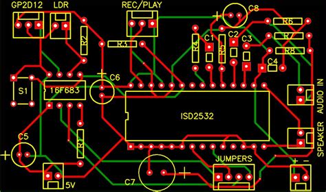
Proper PCB layout is critical for achieving RF immunity in audio amplifiers. By following a few key guidelines, designers can create PCBs that are resistant to RF interference and deliver high-quality audio performance.
Component Placement
As mentioned earlier, proper component placement is essential for achieving RF immunity. Components should be placed as close as possible to their associated ground plane, and any components that are sensitive to RF interference should be shielded or located away from potential sources of interference.
When placing components on the PCB, designers should also consider the length of signal traces. Long traces can act as antennas, picking up external RF interference and introducing noise into the audio signal. To minimize this effect, signal traces should be kept as short as possible, and they should be routed away from potential sources of interference.
Ground Plane Design
The design of the ground plane is another important consideration for achieving RF immunity. As mentioned earlier, the ground plane should be kept as continuous as possible, with no gaps or slots that could create high-impedance paths for ground currents.
When designing the ground plane, designers should also consider the use of a “star” configuration, where all ground connections are made to a single point. This helps to minimize the potential for ground loops and other sources of noise.
Power Supply Design
The power supply is another critical component for achieving RF immunity in audio amplifiers. The power supply should be designed to minimize the amount of high-frequency noise that is introduced into the amplifier, and it should be located away from potential sources of interference.
One common technique for minimizing power supply noise is to use a split power supply, where the positive and negative supply rails are separated by a ground plane. This helps to minimize the potential for crosstalk between the supply rails, reducing the amount of noise that is introduced into the amplifier.
Designers should also consider the use of ferrite beads and decoupling capacitors in the power supply design. These components help to filter out high-frequency noise and prevent it from reaching sensitive circuit components.
Trace Routing
Proper trace routing is also essential for achieving RF immunity in audio amplifiers. Traces should be kept as short as possible, and they should be routed away from potential sources of interference.
When routing traces, designers should also consider the use of guard traces. A guard trace is a trace that is connected to ground and placed alongside a signal trace. The guard trace helps to shield the signal trace from external RF interference, reducing the amount of noise that is introduced into the audio signal.
Shielding
Finally, designers should consider the use of shielding to achieve RF immunity in audio amplifiers. Shielding can be achieved through the use of metal enclosures, shielded cables, and other techniques.
When designing a shielded enclosure, it is important to ensure that there are no gaps or openings that could allow RF energy to leak in. Any openings should be kept as small as possible, and they should be covered with conductive gaskets or other materials to ensure a tight seal.
Frequently Asked Questions
What is RF interference and how does it affect audio amplifiers?
RF interference is electromagnetic interference that occurs at radio frequencies. When an audio amplifier is exposed to RF interference, it can pick up the interference and introduce noise into the audio signal. This noise can manifest as a high-pitched whine, buzzing, or other distortion that can be heard through the speakers or headphones.
What are some common sources of RF interference in audio systems?
There are many potential sources of RF interference in audio systems, including:
- Radio transmitters and receivers
- Mobile phones and other wireless devices
- Power supplies and other electronic components
- Electrical equipment such as motors and transformers
How can I minimize the impact of RF interference on my audio amplifier?
There are several techniques that can be used to minimize the impact of RF interference on audio amplifiers, including:
- Proper grounding and shielding techniques
- The use of filters and decoupling capacitors in the circuit design
- Proper PCB layout techniques, such as component placement and trace routing
- The use of shielded enclosures and cables
What is the difference between star grounding and a ground plane?
Star grounding and ground planes are two different techniques for achieving proper grounding in audio amplifiers.
In star grounding, all ground connections are made to a single point, known as the “star point.” This helps to minimize the potential for ground loops and other sources of noise.
A ground plane, on the other hand, is a large area of copper that is used to provide a low-impedance path for ground currents. Ground planes help to minimize the potential for ground loops and other sources of noise, and they also provide a shield against external RF interference.
Can I completely eliminate RF interference from my audio amplifier?
While it is possible to minimize the impact of RF interference on audio amplifiers, it is not possible to completely eliminate it. There will always be some level of RF interference present in any electronic system, and the goal of RF immunity techniques is to reduce the impact of this interference to an acceptable level.
By using proper grounding and shielding techniques, filters and decoupling capacitors, and proper PCB layout techniques, designers can create audio amplifiers that are highly resistant to RF interference and deliver high-quality audio performance.
Conclusion
RF interference can be a significant problem for audio amplifiers, introducing unwanted noise and distortion into the audio signal. To achieve optimal performance and minimize the impact of RF interference, careful PCB layout techniques must be employed.
By following proper grounding and shielding techniques, using filters and decoupling capacitors in the circuit design, and employing proper PCB layout techniques such as component placement and trace routing, designers can create audio amplifiers that are highly resistant to RF interference.
While it is not possible to completely eliminate RF interference from an audio system, by using these techniques, designers can minimize its impact and deliver high-quality audio performance to their customers.
| Technique | Description | Benefits |
|---|---|---|
| Star Grounding | All ground connections are made to a single point | Minimizes ground loops and noise |
| Ground Planes | Large area of copper used for low-impedance ground path | Minimizes ground loops and provides shielding |
| LC Filters | Inductor and capacitor form resonant circuit to block RF | Filters out high-frequency noise |
| RC Filters | Resistor and capacitor form low-pass filter to block RF | Filters out high-frequency noise |
| Decoupling Capacitors | Capacitor placed between power and ground to filter noise | Minimizes impact of RF on sensitive components |
| Shielding | Use of conductive materials to block or absorb RF | Prevents external RF from reaching sensitive components |
By incorporating these techniques into the PCB layout and circuit design of an audio amplifier, designers can achieve a high level of RF immunity and ensure optimal audio performance.


