

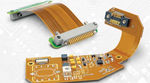
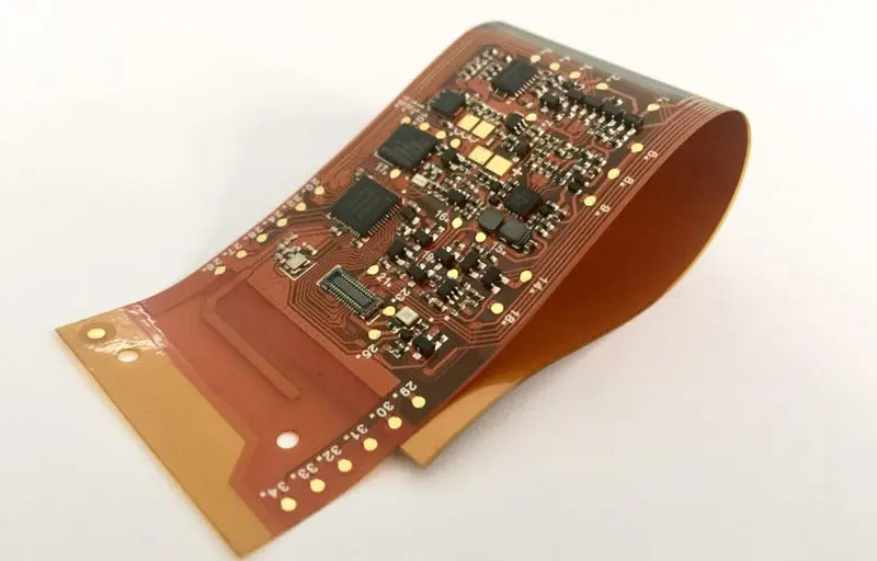
Rigid-flex PCBs, also known as rigid flex circuits, combine rigid and flexible circuit boards into a single structure. They provide solutions for electronic devices and components that require a blend of rigidity for sturdiness and multiple layers for complex circuitry, along with flexibility for motion or convenient packaging.
Industrial rigid flex PCBs are designed to withstand more extreme conditions than commercial rigid flex circuits. They offer durability for motion control, robotic arms, manufacturing equipment, and other automation systems.
Benefits of Industrial Rigid Flex PCBs
Industrial rigid flex PCBs provide a number of advantages over traditional rigid PCBs:
Flexibility and Motion Control
The flex sections allow the PCB to bend and flex. This accommodates movement and complex geometries in automation equipment. Rigid flex can replace hinged connections with continuous circuits.
Space and Weight Savings
By eliminating connectors and allowing dense 3D assembly, rigid flex PCBs save space and weight. This is especially important in motion control arms and small electronics.
Reliability
Rigid flex PCBs have fewer connecting points than rigid PCB assemblies. This results in lower failure rates and improved reliability.
Design Freedom
Rigid flex allows more freedom in designing electronic structures. Curves, folds, and complex shapes are possible.
Cost Efficiency
Rigid flex PCBs can replace expensive cabling and connectors. Automated assembly lowers manufacturing costs.
Materials for Industrial Rigid Flex
Industrial rigid flex PCBs use special materials to provide rugged performance:
- Rigid substrates – FR-4 glass epoxy is commonly used, but polyimide and hi-temp FR-4 provide maximum temperature resistance. Ceramics such as aluminum oxide can be used for extreme environments.
- Flexible substrates – Polyimide films like Dupont Kapton provide the best durability at extreme temps. Other high temp films are also used.
- Bonding layers – Acrylic or epoxy adhesive bonds the rigid and flex layers. These adhesives withstand flexing and vibration.
- Cover layers – Additional polyimide, epoxy, or LCP films protect the circuitry.
- Copper Trace – Copper thickness from 0.5 oz up to 3 oz is used to withstand vibration and thermal cycles.
Design Considerations
Designing an industrial rigid flex PCB requires special considerations:
- Layer Stacking – Rigid sections typically have multiple layers (up to 30+). Flexible sections are usually limited to 1-4 layers.
- Conductors – Traces must be routed from rigid to flex areas. Special geometries are used on flexing traces.
- Flex Bends – Bend radii limits must be considered, along with dynamic flexing parameters.
- Terminations – Connections between rigid and flex sections require specialized terminals and pads.
- Thermal Management – Heat dissipation must be considered, along with thermal expansion coefficients.
- Testing – Rigid flex PCBs require specialized testing procedures like flex cycle life validation.
Proper design is crucial as reworking and repairs of rigid flex is difficult once assembled.
Rigid Sections
The rigid portions of the PCB provide:
- Multiple conductive layers (up to 30+ layers depending on thickness)
- Stiffness for connectors and components
- Flat surface for denser circuitry and components
- Thermal mass for heat dissipation
- Thicker copper (2+ oz) traces for high current
Flexible Sections
The flexible portions of the PCB enable:
- Dynamic motion and flexing
- 3D assembly and complex structures
- Elimination of wired connections
- Thinner, lighter form factors
- High cycle life with proper bend radius
- Typically 1 to 4 layer with thinner copper
Types of Rigid Flex Designs
There are several common configurations for laying out rigid and flex regions:
Discrete Flex
Separate rigid and flex sections interconnected on a single board. Allows complex 3D geometry.
Flex-Rigid Combination
Rigid sections bookend a center flexible circuit. Allows the PCB to fit into tight spaces.
Continuous Flex
Rigid sections are islands in a flexible substrate with conducting traces running between sections. Dynamic continuous bending motion.
Multilayer Rigid Flex
Combines multiple layers of rigid and flexible materials. Allows greater complexity, layer counts, and densities.
Stacked Rigid Flex
Rigid and flex layers are stacked vertically like a sandwich. Used to maximize vertical space.
Folded Flex
Flexible circuit board that is folded into 3D shape. Typically has a single flex layer with rigid sections.
Manufacturing Process
Industrial rigid flex PCBs require specialized fabrication:
Layer Preparation
Rigid layers are fabricated using standard PCB processes: imaging, etching, laminating layers, drilling holes, etc. Flexible layers use polyimide films.
Layer Alignment
Layers are carefully aligned using precision equipment and optical alignment systems. This ensures reliable connections between layers.
Bonding
Layers are bonded using adhesive films. Heat and pressure bonds the layers into a final board.
Via Protection
Vias exposed during flexing are coated with protective coverlay or ink masking to prevent cracking.
Solder Mask
A solder mask is applied to avoid solder bridging between traces. Selective screening ensures quality solder joints.
Finishing
Edge trimming, contouring, hole plugging, and protective coating provide the finished rigid flex PCB.
Applications of Industrial Rigid Flex
Industrial rigid flex PCBs are designed for severe environments and rugged applications:
Robotics and Motion Control
Arms, joints, and grippers benefit from rigid flex flexibility, constant connections, and dense circuit layers.
Industrial Equipment
Printers, assembly equipment, process systems use rigid flex for interconnect and motion. Vibration resistance prevents downtime.
Automotive Manufacturing
Robotic arms on assembly lines use rigid flex to reach into tight spaces and make continuous connections.
Aerospace and Defense
Military systems, guidance equipment, and engine electronics must withstand extreme temperatures and g forces.
Medical Equipment
Imaging machines, robotic surgical tools, and diagnostic systems integrate rigid flex technology.
Consumer Electronics
Some high-end consumer devices employ rigid flex PCBs on a limited basis for space savings and reliability.
Pros and Cons of Rigid Flex PCBs
Here are some key advantages and disadvantages when considering rigid flex PCBs:
Pros
- Dynamic flexing ability
- Unlimited shapes and geometries
- Increased reliability
- Space and weight savings
- Eliminates wired connections
- Simplifies complex designs
- Cost effective vs assemblies
Cons
- Higher initial design cost
- Potential difficulty troubleshooting
- Challenging repair once assembled
- Limited number of rigid/flex layers
- Production is more complex
- Advanced design experience needed
FQA
Here are answers to some frequently asked questions about industrial rigid flex PCBs:
How many flex cycles can rigid flex withstand?
With proper design, rigid flex PCBs can achieve 1 million+ flex cycles. Factors include flex material, trace geometries, and bend radii.
Can components be mounted directly on the flex area?
Smaller surface mount components can be mounted on the flex area directly. Larger through hole components are only mounted on rigid sections.
How small can the bend radius be?
Bend radii down to 3 times the total board thickness are possible, but larger radii improve life cycles. Dynamic or rolling flexing requires larger bend radii.
What are typical layer counts?
Rigid sections can have up to 30+ layers like normal PCBs. Flex sections typically max out at 4 layers due to flexibility requirements.
Can rigid flex PCBs be double-sided?
Yes, circuitry and components can be placed on both sides in the rigid sections, just like a standard PCB. Flex sections are limited to single-sided.
This 2000+ word article summarizes the key points about industrial rigid flex PCBs, including materials, design considerations, manufacturing, applications, pros/cons, and common FAQs. Rigid flex technology provides unique benefits for automation and machinery requiring flexible and robust interconnect solutions. With careful design tailored to environmental conditions and motion requirements, rigid flex PCBs can improve reliability and capability.