

Introduction to Semi-Flex PCBs
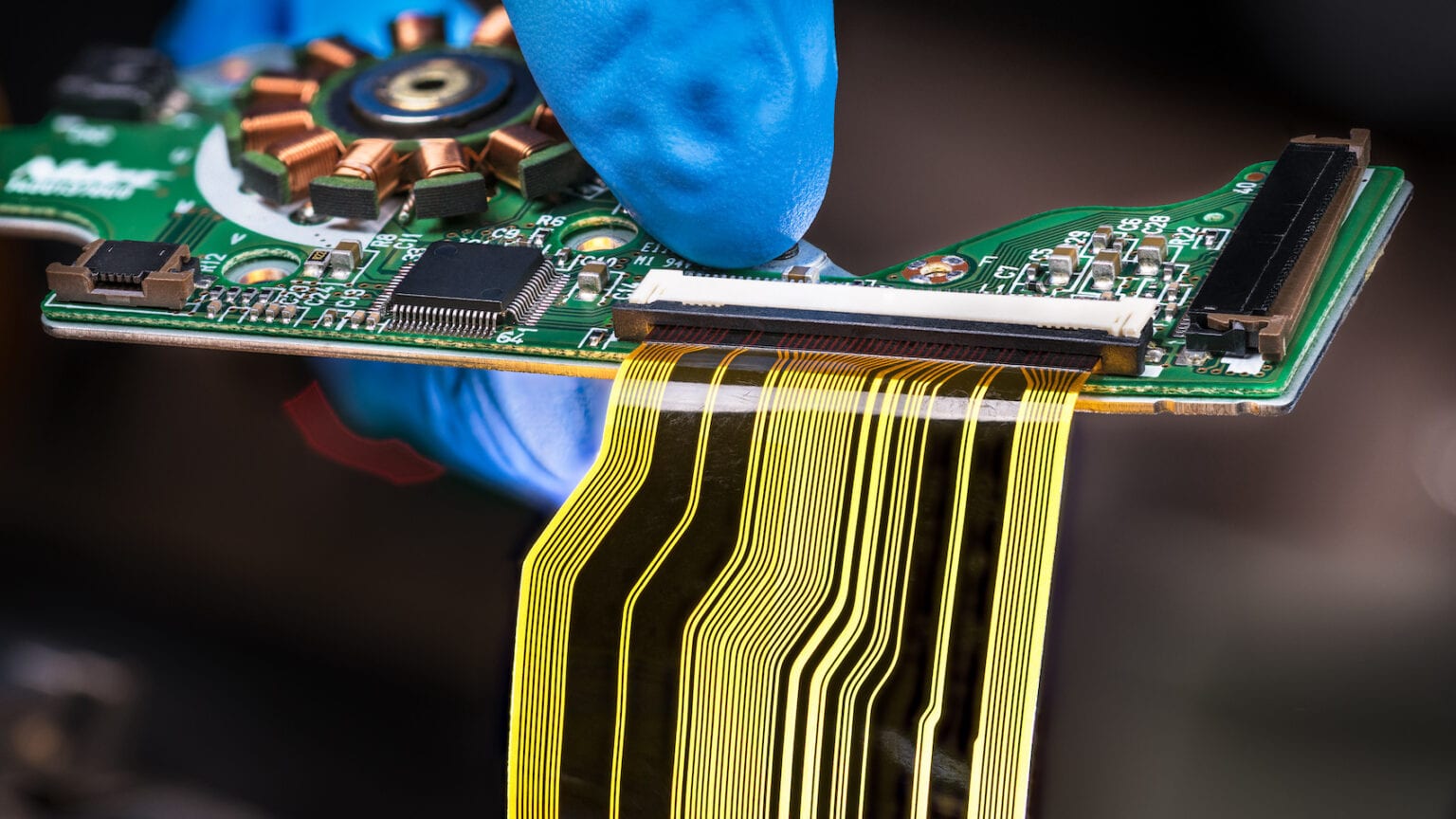
A semi-flex printed circuit board (PCB) is a type of circuit board that combines the characteristics of both rigid PCBs and flexible PCBs. As the name suggests, semi-flex PCBs offer some degree of flexibility but are not as flexible as pure flexible PCBs.
Semi-flex PCBs contain flexible substrate materials like polyimide along with reinforced layers to provide rigidity and support. This allows them to be bent and flexed to a certain degree without damage while still maintaining their shape.
Characteristics of Semi-Flex PCBs
- Can be bent and flexed to conform to 3D shapes
- More rigid than pure flex PCBs but not as rigid as FR4 PCBs
- Often have flex areas connected by rigid sections
- Uses flexible substrates like polyimide
- May have embedded rigid layers for support
- Suitable for dynamic flexing applications
- Used where some flexing is required but a fully flexible PCB is not needed
Semi-flex PCBs provide the perfect balance of flexibility and rigidity for many electronic devices and components that require dynamic flexing or fitting into irregular shapes. They are commonly used in various industries like automotive, aerospace, medical devices and more.
Applications and Uses of Semi-Flex PCBs
Semi-flex PCBs are suitable for a wide range of applications that require some degree of flexibility or fitting into tight spaces:
Wearable Electronics
For wearable devices like smart watches, fitness trackers and VR headsets, semi-flex PCBs can conform to the natural contours of the human body. This allows for better ergonomics and comfort. The rigid sections provide support and component mounting.
Medical Devices
Medical devices like hearing aids and portable patient monitoring systems are often required to flex and bend to anatomical shapes. Semi-flex PCBs are used extensively to meet the flexibility along with circuit integrity and reliability.
Automotive Electronics
Due to cramped spaces and contours in automotive interiors, semi-flex PCBs are ideal for control panels, LED displays and in-car entertainment systems by bending around seats and fittings.
Robotics and UAVs
For moving joints and appendages in robots and UAVs, semi-flex PCBs can enable twisting and turning by folding in specific zones while rigid areas mount electronics.
Consumer Electronics
Various handheld consumer electronics like mobile phones, cameras and portable gaming systems use semi-flex PCBs to connect various rigid PCBs and route signals through hinged and dynamic sections.
In addition to the above applications, semi-flex PCBs are also found in POS terminals, calculators, hard disk drivers and many other electronic devices where some degree of flexibility is required. The combination of flex and rigid gives designers options to integrate circuits in ways not possible with rigid boards alone.
How Are Semi-Flex PCBs Constructed
Semi-flex PCBs can be constructed in several ways by combining flexible printed circuits (FPC) with rigid FR4 layers:
Rigid-Flex PCBs
This type consists of flexible circuits extending or branching out from rigid PCB sections allowing them to be folded or bent. The rigid regions provide structural support for mounting components while the flex areas connect or route signals between components.
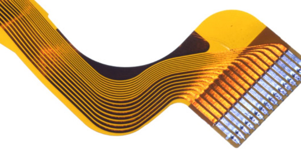
Rigid flex PCB with flexible circuits extending from rigid section.
Flex-Rigid PCBs
In this arrangement, the primary substrate is a flexible circuit material with islands or sections of rigid FR4 bonded to it. Components are mounted on the rigid islands while flexible layers route signals between islands.
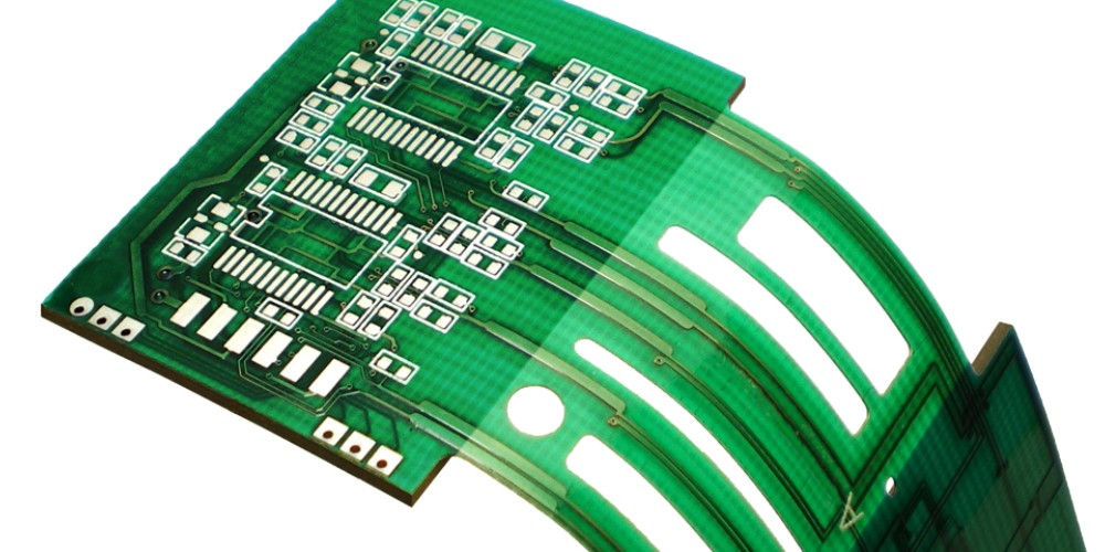
Flex rigid PCB with rigid islands.
Multi-Layer Semi-Flex PCBs
These have alternating layers of flex and rigid substrates bonded together into a multi-layer board. They allow mounting components on both sides while providing multiple layers for routing traces.
The construction methods used include layer bonding, pick and place assembly and soldering. Advanced PCB manufacturing processes like laser direct imaging (LDI) are used to achieve fine trace widths and spacing.
Design Guidelines for Semi-Flex PCBs
Designing semi-flex PCBs requires following certain guidelines to ensure flex reliability and prevent failures:
- Minimize rigid sections: Rigid sections should be limited to areas where component mounting is required. This improves overall flexibility.
- Carefully plan rigid-flex interfaces: Use teardrop shapes at the interface between rigid and flex areas to prevent stress concentration and cracking.
- Avoid sharp corners or angles: Angles cause stress points leading to fractures. Use rounded corners with a minimum 5mm radius.
- Design flex area for dynamic bending: Ensure the flexing regions bend along the neutral axis to minimize strain. Keep minimum bend radius >10X material thickness.
- Use stabilized flexible materials: Use robust flexible materials like polyimide that are designed for continual flexing. Normal FR4 may crack.
- Account for different material properties: Relative to FR4, flex materials have lower modulus of elasticity. Adjust spacing and trace widths accordingly.
- Implement strain relief: Use anchoring, slack loops and adhesive filling to provide strain relief in high stress areas.
Following these guidelines will yield reliable semi-flex PCB designs that avoid common failure modes like fracturing and tearing during use. Prototyping and testing is also critical.
Key Manufacturing Processes
Advanced PCB manufacturing techniques are required to produce quality semi-flex PCBs:
Photolithography: Uses laser direct imaging (LDI) and photomasks to pattern thin copper layers and trace geometries down to 5/5 mil line/space.
Etching: Etches away unwanted copper to leave behind finely patterned traces and pads.
Layer Alignment: Aligns layers using precision equipment for accurate registration between layers.
Layer Bonding: Bonds alternating flexible and rigid layers together using adhesive and heat or laser lamination.
Hole Drilling: Drills precision holes for vias and through-holes using mechanical or laser drills.
Plating and Coating: Electrolytic and electroless copper plating to coat drilled holes, build up layers and add solder mask/silkscreen.
Testing and Inspection: Testing for opens/shorts, continuity, registration accuracy and bend radii.
Combining these processes enables reliable construction of complex multi-layer semi-flex PCBs.
Pros and Cons of Semi-Flex PCBs
Here are some key advantages and disadvantages of semi-flex PCBs:
Pros
- Combines flexibility and rigidity
- Can conform to 3D shapes and enclosures
- Allows creative packaging solutions
- Good for high vibration/impact environments
- Saves space compared to rigid boards
- Allows dynamic flexing motions
- Easier to manufacture vs. pure flex PCBs
Cons
- More expensive than rigid PCBs
- Design complexity due to flex/rigid interfaces
- Needs careful mechanical stress analysis
- Requires advanced manufacturing equipment
- Limited choices for some components
- Difficult to modify or repair after assembly
- Requires expertise to manufacture reliably
Cost Factors
Several factors impact the costs of semi-flex PCBs:
- Number of layers
- Board thickness
- Board size
- Quantity being produced
- Number of flex layers
- Complexity of flex/rigid interfaces
- Tightness of trace/space
- Special materials needed
- Testing requirements
- Production yields
In general, costs run 20-50% higher than equivalent rigid PCBs. But the benefits outweigh the costs for most applications requiring some flexibility.
Q&A on Semi-Flex PCBs
Here are some common questions and answers about semi-flex PCBs:
Q: What are some key differences between rigid, flex, and semi-flex PCBs?
A: Rigid PCBs use FR4 and have no flexibility. Flex PCBs use polyimide and can be bent repeatedly to tight radii. Semi-flex combine both rigid and flex layers to allow some dynamic bending while having rigid areas for mounting.
Q: What are some typical substrates used in semi-flex PCBs?
A: Polyimide is most common flex substrate. Rigid sections use FR4 or materials like polycarbonate or PEN. Adhesives bond the layers.
Q: What are some ways to improve reliability of dynamic flexing regions?
A: Use robust flexible materials, implement strain relief features, avoid sharp bends, and test prototypes thoroughly under lifecycle motions.
Q: How are components assembled onto semi-flex PCBs?
A: SMT assembly is used to mount components onto rigid areas. Care is taken during flexing not to damage brittle components. Through-hole parts are avoided.
Q: What are some examples of industries using semi-flex PCBs?
A: Key users include consumer electronics, wearables, automotive, aerospace, medical, robotics, and instrumentation. The need for flexibility and compactness drives adoption.
Conclusion
Semi-flex PCBs occupy the middle ground between rigid boards and fully flexible circuits. With both flex and rigid areas, they provide the ideal solution for products and components needing to dynamically bend and flex while maintaining circuit integrity.
Careful design and manufacturing is needed to withstand mechanical stresses and prevent flex failures. When produced properly, semi-flex PCBs enable innovative packaging methods not possible with rigid boards.
Continued improvements in flex materials and fabrication will expand semi-flex applications in cutting-edge industries like wearables, IoT devices and flexible displays.