


Introduction
Flex circuits, also known as flexible printed circuits (FPCs), are a type of printed circuit board that can bend and flex. They are made from flexible materials like polyimide and laminated copper foil. Flex circuits provide several advantages over rigid circuit boards, including flexibility, space and weight savings, and improved reliability in dynamic environments. However, designing and prototyping flex circuits requires some specialized considerations compared to rigid boards. In this article, we will discuss the flex circuit prototyping process, including design, materials selection, fabrication methods, assembly, and testing.
Designing Flex Circuits
The design process for a flex circuit is in many ways similar to that of a rigid printed circuit board (PCB). It starts with schematic capture and simulation, followed by physical layout and routing. However, there are some important differences to consider:
Layer Stackup
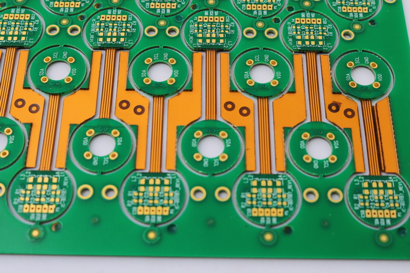
Flex circuits use different materials than rigid FR-4 PCBs. Most flex circuits consist of alternating layers of flexible polyimide and laminated copper foil. The cross-section layer stackup must be designed appropriately.
Flexibility
The circuit layout must account for the dynamics of the flexing itself. Traces should be routed along the neutral bend axis whenever possible. And special caution should be used where traces cross gaps or slots in the substrate.
Adhesion
Proper adhesion between layers is critical on flex circuits. Adhesive selection and lamination processes need to withstand flexing stresses.
Stiffeners
Discrete components will need stiffener supports or carriers to withstand flexing. Stiffeners also help manage stresses where the flex circuit interfaces with rigid components.
Tolerances
Flex circuit fabrication generally has tighter tolerances than rigid PCBs. This should be considered during the physical layout.
Material Selection
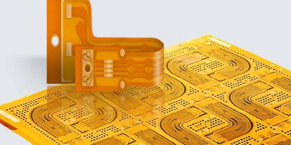
Polyimide films are most commonly used as the flexible dielectric substrate for flex circuits. There are a variety of options:
- Kapton – Dupont branded polyimide film, available in various thicknesses. Common for simpler flex circuits.
- Apical – An alternative polyimide film comparable to Kapton.
- UPISEL – Polyimide with improved dimensional stability. Used for circuits with tight tolerance requirements.
- LG Polyimide – Affordable polyimide option. Can replace Kapton for cost savings.
The copper foil is laminated onto the polyimide to form the conductive traces. 1 oz and 2 oz copper foils are typical. Adhesives are used to bond the layers together. Popular options are acrylic, epoxy, or polyimide adhesives. The material stackup should be designed to meet the application requirements for flexibility, thermal performance, electrical properties, and reliability.
Fabrication
Small-scale flex circuit prototypes can be fabricated using common PCB methods. However, specialized techniques are preferred for production-level flex circuits.
Photolithography
A photolithographic process can produce high density traces and features. Liquid photoresist is applied, exposed, and developed to form the circuit pattern. Then the copper foil is etched. Photolithography allows fine features down to 6 mils. But it requires special fixturing for handling the thin flexible substrate.
Laser Direct Imaging (LDI)
Laser direct imaging uses a focused laser to ablate away unwanted copper, isolating the desired traces. LDI is quicker than photolithography and ideal for rapid prototyping. Feature size is limited to about 10 mils.
Printed Electronics
Printed electronics methods like inkjet printing can deposit conductive inks directly onto the substrate. This eliminates the need for etching and enables additive rather than subtractive processes. Printed electronics is better suited to less complex flex circuits and can produce features down to 20 mils.
Assembly
Several specialized processes are used to assemble components onto flex circuits:
Reflow Soldering
Reflow soldering can be used to mount SMT components. The flex circuit is fixtured to keep it stable during solder reflow. Parts may require adhesives to reinforce solder joints.
Conductive Adhesives
SMT components can be mounted with conductive epoxies and anisotropic conductive films. These adhesives provide electrical interconnects and mechanical attachment. Flex circuits experience less solder joint strain when using conductive adhesives.
Mechanical Attachment
Through-hole components can be attached to flex circuits using crimp terminals, eyelets, rivets, or various mechanical fasteners. Stiffeners help reinforce the solder joints. Careful part selection is necessary, as leaded components introduce stresses.
Thermal Compression Bonding
For extreme environments, components may need thermal compression bonding rather than soldering. Heat and pressure create fusion bonds for reliable connections. This is common with space-grade electronics.
Testing and Inspection
Thorough inspection and testing is important when prototyping flex circuits:
- Visual inspection under magnification checks for defects, alignment, and acceptable fill levels for the traces.
- Dimensional inspection verifies PCB features have been fabricated to the specified size and position tolerances.
- Netlist testing confirms electrical connectivity and isolates any opens or shorts.
- Continuity testing using a multimeter checks for broken traces that may not be detected in a netlist test.
- Circuit functioning should be validated before and after simulated flexing. Verify components remain adhered and electrically connected.
- Repeat testing over several flex cycles characterizes flex reliability under dynamic bending stresses.
Conclusion
Flex circuits require careful design, material selection, fabrication, assembly, and testing to account for their unique properties and demands. Following the guidelines in this article will help developers build successful flex circuit prototypes and accelerate their projects from design concept to functional prototype.
Summary of Key Flex Circuit Prototyping Considerations:
- Optimize layout for flexibility – neutral bend axis, avoid crossing gaps
- Use polyimide dielectric materials
- Select 1-2 oz rolled annealed copper foils
- Laser direct imaging offers fast fabrication
- Reflow solder components with adhesive reinforcement
- Conduct final inspection under magnification
- Test board function before, during, and after flexing
FAQ
What are some typical applications for flexible printed circuits?
Some common uses of flex circuits include:
- Consumer electronics – Cell phones, laptops, printers
- Automotive – Instrument panels, engine controls, sensors
- Medical – Hearing aids, imaging equipment
- Industrial – Robotics actuators, factory automation
- Aerospace and military – Avionics, satellites, missiles
The small, lightweight, and dynamic nature of these systems makes flex circuits well suited for interconnections.
What design software tools are used for flex circuit layouts?
Any PCB layout software that supports flex-rigid boards can be used. Common options are Altium Designer, Cadence Allegro, and Mentor Xpedition. These tools allow defining flexible substrates, layer stackups, and bend areas.
Can flex circuits have plated through holes like a rigid PCB?
Yes, flex circuits can support plated through holes (PTHs) to mount leaded components. The holes are drilled or punched through the stackup then plated with copper. Stiffeners help support the leads. Vias with filled blind holes can also be used.
What are some best practices for dynamic flex testing?
Use sharp bend radii between 1-2mm to induce maximum stresses. Apply 100 flex cycles as a typical starting point. Monitor effects of flexing via continuity testing, electrical function tests, and visual inspection. Ensure test conditions simulate actual use – temperature, humidity, orientation.
How are components attached to the flexible substrates?
Reflow soldering, conductive adhesives, mechanical fasteners, and thermal compression bonding represent common flex circuit assembly techniques. The method depends on component types, complexity, required reliability, and environmental demands.