


Introduction to Crystal Oscillators
A crystal oscillator is an electronic circuit that uses the mechanical resonance of a vibrating crystal of piezoelectric material to create an electrical signal with a precise frequency. This frequency is commonly used to keep track of time, provide a stable clock signal for Digital Integrated Circuits, and to stabilize frequencies for radio transmitters and receivers.
Types of Crystal Oscillators
There are several types of crystal oscillators, including:
- Pierce oscillator
- Colpitts Oscillator
- Hartley oscillator
- Clapp oscillator
In this article, we will focus on building a Pierce crystal oscillator circuit.
Components Required
To build a crystal oscillator circuit, you will need the following components:
| Component | Value/Type |
|---|---|
| Crystal | 32.768 kHz |
| Resistor | 1 MΩ |
| Capacitor | 22 pF |
| Capacitor | 22 pF |
| NAND Gate | 74HC00 |
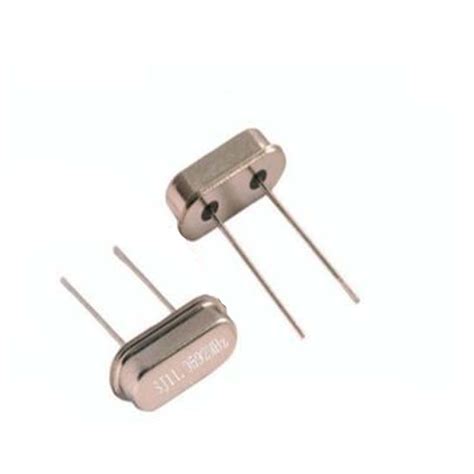
Crystal Selection
The heart of the crystal oscillator circuit is the crystal itself. Crystals are available in various frequencies, but for this example, we will use a 32.768 kHz crystal, which is commonly used in Real-Time Clock applications.
Resistor and Capacitor Selection
The resistor and capacitors in the circuit are used to bias the NAND gate and provide the necessary feedback for oscillation. The values of these components can be adjusted to fine-tune the oscillator’s performance.

Circuit Diagram
Here is the circuit diagram for the Pierce crystal oscillator:
              +---------+
              |         |
   +-----+    |  74HC00 |    +-----+
   |     |    |         |    |     |
   |     |----+         +----+     |
   |     |    |         |    |     |
   | 1MΩ |    +---------+    | 22pF|
   |     |                   |     |
   +-----+                   +-----+
      |                         |
      +----+         +----+     |
           |  32kHz  |    |     |
      +----+  XTAL   +----+     |
      |    |         |          |
      |    +---------+          |
      |                         |
     ---                       ---
     GND                       GND

Step-by-Step Guide
- Begin by connecting the crystal between the input and output of the NAND gate. The crystal should have a small capacitor (22 pF in this case) connected in parallel with it.
- Connect a 1 MΩ resistor between the input of the NAND gate and the positive supply voltage (VCC).
- Connect another 22 pF capacitor between the output of the NAND gate and ground.
- Connect the remaining inputs of the NAND gate to VCC to ensure they are in a known state.
- The output of the NAND gate will now produce a square wave with a frequency of 32.768 kHz.

Adjusting the Oscillator
If the oscillator fails to start or is unstable, you may need to adjust the values of the resistor and capacitors. Increasing the resistor value will increase the gain of the oscillator, while decreasing the capacitor values will increase the frequency of oscillation.
Applications of Crystal Oscillators
Crystal oscillators are used in a wide range of applications, including:
- Timekeeping: Crystal oscillators are often used in real-time clocks and watches to keep accurate time.
- Microcontrollers: Many microcontrollers use crystal oscillators to provide a stable clock signal for their internal operations.
- Radio communication: Crystal oscillators are used to generate stable carrier frequencies for radio transmitters and receivers.
- Audio equipment: High-quality audio equipment often uses crystal oscillators to ensure accurate audio sampling rates.
Advantages of Crystal Oscillators
Crystal oscillators offer several advantages over other types of oscillators:
- High accuracy: Crystal oscillators are known for their high accuracy and stability, making them ideal for applications that require precise timing.
- Low power consumption: Crystal oscillators typically consume very little power, making them suitable for battery-powered devices.
- Small size: Crystals are available in small packages, allowing for compact oscillator designs.
Disadvantages of Crystal Oscillators
Despite their many advantages, crystal oscillators do have some limitations:
- Limited frequency range: Crystals are only available in a limited range of frequencies, which may not be suitable for all applications.
- Susceptibility to temperature changes: The frequency of a crystal oscillator can be affected by changes in temperature, which may require additional temperature compensation circuitry.
- Fragility: Crystals are fragile and can be damaged by mechanical shocks or vibrations.
Troubleshooting Crystal Oscillator Circuits
If your crystal oscillator circuit is not working as expected, here are some troubleshooting tips:
- Check the power supply: Ensure that the circuit is receiving the correct supply voltage and that the power supply is clean and stable.
- Verify component values: Double-check that the resistor and capacitor values are correct and that the components are functioning properly.
- Inspect the crystal: Check that the crystal is properly connected and not damaged. If possible, try replacing the crystal with a known working one.
- Check the layout: Make sure that the circuit layout is clean and that there are no shorts or open connections. Pay attention to the placement of components and the routing of traces to minimize Stray Capacitance and inductance.
Frequently Asked Questions (FAQ)
- Q: What is the purpose of the resistor in the crystal oscillator circuit?
A: The resistor in the crystal oscillator circuit is used to bias the NAND gate and provide the necessary gain for the oscillator to start and maintain oscillation. - Q: Can I use a different type of logic gate instead of a NAND gate?
A: Yes, you can use other types of logic gates, such as an inverter or a buffer, to build a crystal oscillator circuit. However, the specific circuit configuration may need to be adjusted accordingly. - Q: What happens if I change the values of the capacitors in the circuit?
A: Changing the values of the capacitors in the crystal oscillator circuit will affect the frequency of oscillation. Decreasing the capacitor values will increase the frequency, while increasing the values will decrease the frequency. - Q: Can I use this circuit for high-frequency applications?
A: The Pierce crystal oscillator circuit is generally suitable for low to medium frequency applications. For high-frequency applications, other oscillator designs, such as the Colpitts or Clapp oscillator, may be more appropriate. - Q: How do I connect the output of the crystal oscillator to other circuits?
A: The output of the crystal oscillator can be connected to other circuits using a buffer or a level translator, depending on the input requirements of the receiving circuit. This helps to isolate the oscillator from any load effects and ensure a clean, stable output signal.
Conclusion
In this article, we have explored the fundamentals of crystal oscillators and provided a step-by-step guide on how to build a Pierce crystal oscillator circuit. We discussed the components required, the circuit diagram, and the process of adjusting and troubleshooting the oscillator.
Crystal oscillators are essential components in many electronic applications, offering high accuracy, low power consumption, and small size. By understanding the principles behind crystal oscillators and learning how to build them, you can incorporate these versatile circuits into your own projects and designs.
Remember to always consider the specific requirements of your application when selecting components and designing your crystal oscillator circuit. With the knowledge gained from this article, you should be well-equipped to start experimenting with crystal oscillators and unlocking their potential in your electronic projects.