


15 Commonly Used Components on PCBs for Beginners
Introduction
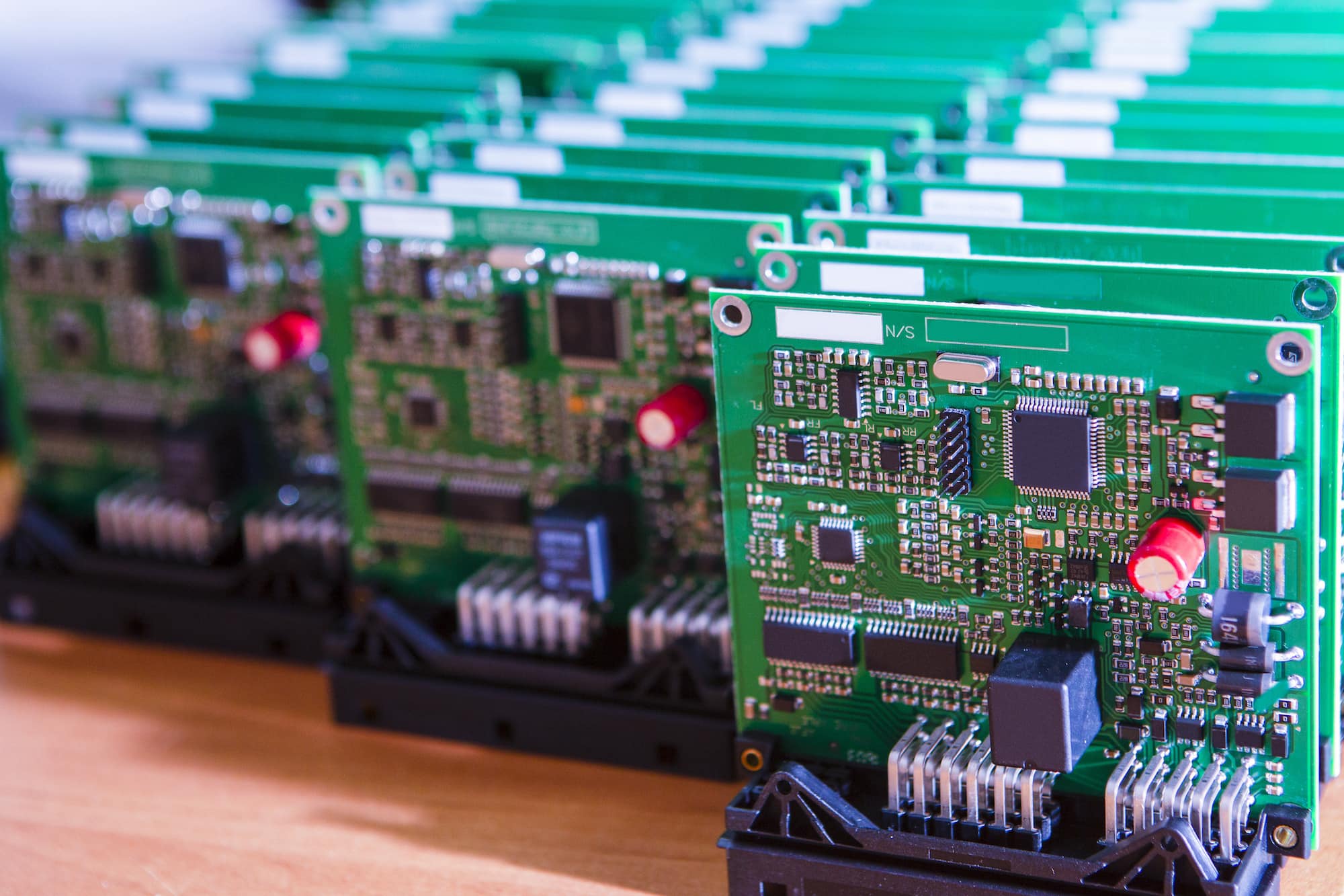
Printed circuit boards (PCBs) form the foundation of most modern electronic devices. They provide the physical structure and connections between components that allow a circuit to function. For beginners learning about PCB design and electronics, it’s important to become familiar with some of the most common components found on PCBs.
In this article, we will provide an overview of 15 different components that are widely used on PCBs targeted at beginners. For each component, we will cover:
- A brief description of what the component is and what it does
- Symbol – The schematic symbol used to represent the component
- Package – The physical packaging or form factors available
- Example applications – Where you’re likely to encounter the component
Understanding these basic passive and active components will provide a solid basis for more advanced PCB design and electronics troubleshooting down the road. So let’s get started!
Resistors
Description
A resistor is a passive electronic component that resists the flow of electric current. Resistors have a specific resistance value, measured in ohms (Ω), that determines how much they resist current flow. By limiting and controlling the flow of electrons, resistors can be used to adjust signals, divide voltages, and more.
Symbol
Packages
Axial, surface mount chip, surface mount array
Applications
Voltage division, current limiting, pull up/pull down, damping and termination
Capacitors
Description
A capacitor is a passive electronic component capable of storing electrical charge and energy. Capacitors essentially consist of two conductors separated by an insulator or dielectric. When voltage is applied, positive and negative charges accumulate on each conductor, storing energy in an electric field between the two.
SymbolPackages
Radial and surface mount ceramics, electrolytic, tantalum, film
Applications
Decoupling, filtering, energy storage, timing and frequency tuning
Inductors
Description
An inductor is a passive electronic component that stores energy in the form of a magnetic field. It is basically just a coil of conductive wire. When current flows through the inductor, a magnetic field is generated around each turn of the coil. This field stores energy that can be released back into the circuit later.
Symbol
Packages
Axial, surface mount, shielded
Applications
Filters, oscillators, energy storage in switched mode power supplies
Diodes
Description
A diode is an electronic component with two terminals that allows current to flow in only one direction. This asymmetric conduction makes diodes suitable for applications like rectifiers to convert AC to DC. Diodes can also be used for other functions like clipping, clamping, switching and voltage regulation.
Symbol
Packages
Axial (DO-41), surface mount DO-214/SOD
Applications
Rectification, clipping and clamping, voltage regulation, ESD protection
Transistors
Description
Transistors are semiconductor devices used to amplify electrical signals and act as an electrically controlled switch. They have three terminals – a base, collector and emitter. A small current flowing between base and emitter can be used to control a much larger current between collector and emitter. This makes transistors key components in amplifier circuits.
Symbol
Packages
TO-92, SOT-23, various surface mount packages
Applications
Amplifiers, oscillators, switched and drivers
Integrated Circuits
Description
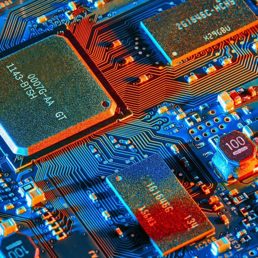
Integrated circuits, or ICs, contain microcircuits with components like transistors and resistors fabricated on a semiconductor material like silicon. Multiple components can be integrated within a compact IC package to achieve complex functions. ICs are central to most electronic systems, with both analog and digital applications.
Symbol
Packages
DIP, SOIC, QFP, BGA and other SMT packages with multiple pins
Applications
Microprocessors, microcontrollers, memory, voltage regulators, amplifiers, AD/DA converters, and more
Light Emitting Diodes (LEDs)
Description
LEDs are semiconductor devices that emit light when current flows through them. Unlike filament-based lamps, they are very efficient and long-lasting, making LEDs the choice for displays, indicators and lighting. LEDs only emit light in one direction and have polarity, so require careful PCB layout.
Symbol
Packages
Axial, surface mount, high power
Applications
Indicator lights, illumination, displays, backlighting
Resistor Networks/Arrays
Description
Resistor networks integrate multiple individual resistors into a single package. The resistors can be arranged in series, parallel or complex combinations within the network. Using a resistor network simplifies PCB layout compared to individual components. Values are tightly matched since resistors are co-fabricated on the same substrate.
Symbol
Packages
DIP, SOIC and other surface mount packages
Applications
Terminations, voltage division, pull up/down, filtering
Terminal Blocks
Description
Terminal blocks provide an easy way to make electrical connections. Screw terminals allow individual wires to be securely attached without soldering. Multiple sizes and styles with different number of contacts are commonly found on PCBs for interconnecting boards or external wiring. Many choices exist for pitches and termination types.
Symbol
Packages
Through-hole and surface mount blocks with multiple contacts
Applications
External wiring interconnections
Buttons and Switches
Description

Buttons, switches and keys are used as user interface devices to manually turn circuits on/off, choose modes, provide inputs and more. Many varieties exist including push button, rocker, DIP switches and others with electrical and mechanical specifications to suit different applications.
Symbol
Packages
Various through-hole and SMT buttons/switches/keypads
Applications
User inputs, control signals, I/O interfaces
Fuses
Description
Fuses provide overcurrent protection and circuit safety. They contain a thin wire link that melts and opens if current exceeds ratings, breaking the connection. Resettable fuses automatically reconnect once fault clears. Various fuse sizes available from 1206 chips to large power line fuses.
Symbol
Packages
Glass body axial, multilayer chip, resettable polymer types
Applications
Overcurrent and short circuit protection
Test Points
Description
Test points provide easy access to test signals on a PCB using an oscilloscope or multimeter probe. They include pads, holes plated through, loops and clips. Test points minimize damage to circuit and tracks during testing. Often found near measurement critical components that require calibration or debugging.
Symbol
Packages
Through-hole pads/loops, SMT pads
Applications
Testing and measurement points
Crystals and Oscillators
Description
Crystals are piezoelectric components that oscillate at precise frequencies when voltage is applied. This stable oscillation enables them to generate clock signals and set frequencies extremely accurately for radios, microcontrollers and other devices. Crystals come in metal or ceramic housings with various frequencies.
Symbol
Packages
Metal can, ceramic SMD, HC-49 leaded
Applications
Clock signal generation, radio frequency setting, microcontrollers
Connectors
Description
Connectors allow removable interconnections between a PCB, cables and other boards or devices. A huge variety of standardized connector types exist including D-Subminiature, RJ45, USB, edge card/finger connectors and more. Connector choice depends on signals, frequencies, mating cycles durability needs.
Symbol
Packages
D-Sub, RJ45, USB, SIM card slot, edge fingers, board stackers
Applications
Board to board interconnections, cables/wiring, removable modules
Headers and Female Sockets
Description
Headers and sockets provide an easy way to interface PCBs. Headers contain multiple male pins in plastic housings while sockets have corresponding female receptacles. Combined they enable stackable and removable connections between boards. Available with different numbers of ways from single to dual row 0.1 inch pitch.
Symbol
Packages
Through-hole and surface mount headers/sockets
Applications
Board stacking, removable daughterboards, prototyping
Optocouplers
Description
Optocouplers contain an LED coupled with a light sensitive transistor to provide electrical isolation while still transferring signals between circuits. This is useful for isolating sensitive circuitry. Optocouplers have various transfer properties from coupling LED brightness to sensor current gain and bandwidth.
Symbol
Packages
DIP, SOIC, SMT
Applications
Signal isolation, circuit separation for noise reduction
Voltage Regulators
Description
Voltage regulators generate and maintain a constant DC output voltage irrespective of changes in load current demands or input voltage fluctuations. They are key for powering sensitive analog and digital circuits. Regulators come as fixed linear types or switch mode step downs. Availability in small SMD packages with various output voltage, current and fault tolerance make them convenient and reliable to use.
Symbol
Packages
3 pin linear, adjustable, SDIP, buck SMT regulators
Applications
Voltage supply regulation, reference voltages
Summary
This covers 15 of the most common passive and active components that you are likely to find on many beginner-friendly PCB projects. Being able to recognize and understand them is an important first step to designing and assembling your own circuits or prototyping boards.
While we’ve focused on through-hole and surface mount packages in this article, you may also encounter other emerging component packages. These include wafer level scale packages (WLSPs) and integrated passive devices (IPDs) which offer higher densities.
FQA
What are the advantages of using a resistor network versus individual resistors?
Using a resistor network has several advantages compared to individual resistors:
- Saves PCB area since multiple resistors are integrated within a single IC package
- Reduces assembly cost and time since only one component needs to be mounted versus multiple discrete resistors
- Resistor values track closely thanks to co-fabrication on the same silicon substrate
- Flexibility to have different array configurations like series/parallel networks in one package
- Common combos like pull up/down premade or terminations available off the shelf
Why do circuits need capacitors given their simple structure?
While basic in construction, capacitors are crucial in circuits because of their ubiquitous role for:
- Storing and releasing energy over short periods to stabilize power supplies during transients
- AC coupling between stages and blocking DC signals
- Smoothing rectified signals by filtering ripple
- Timing elements for setting oscillator frequencies and response times
- Noise filters to prevent coupling between sensitive nodes
This makes high frequency analog, digital, mixed signal designs dependent on the right capacitors.
What is the difference between linear and switch mode voltage regulators?
The main differences are:
Linear regulators:
- Simple circuits consisting of references, error amplifiers, pass transistors
- Regulates by burning excess voltage as heat maintaining fixed output
- Large dropout voltages, less efficient with heat sinks often required
- Low noise, stable and easy to use
Switch mode regulators:
- More complex pulse width modulation conversion circuits
- Steps input down efficiently as needed through inductors/transformers
- Small dropout, higher efficiency often 90%+ with smaller sizes
- Generates more EMI requiring good layout and filtering
- Low cost but can be complex to design properly for stability
So in summary, linear types are simpler but less efficient while switch modes are more complex but higher efficiency and smaller.
Why are proper resets and timeouts needed for microcontrollers interacting with peripherals like EEPROMs?
Electrically erasable programmable read only memories (EEPROMs) used with microcontrollers require resets and timeouts because:
- EEPROMs need a proper reset sequence to initialize after power up
- EEPROM writes can take up to several milliseconds to complete
- Microcontrollers run much faster than EEPROM access times
- So timeouts are needed between writes to allow completion
- And resets avoid interrupting midway writes causing data corruption
Without timeouts or interrupts signaling writes done, crashes can happen. So fail-safe design with MCU to EEPROM interaction requires good firmware interface handling these timings.
How does using a 32.786 kHz watch crystal improve accuracy versus ceramic resonators in small microcontroller circuits?
Compared to ceramic resonators:
- Watch crystals aging only 30ppm vs 250-3000 ppm/year improves long term accuracy
- Temperature drift of +/- 20ppm over -10 to 60°C vs -250 to +500ppm much better
- Initial tolerance +/-20ppm compared to 0.5-1.5% or 5000 to 15000ppm tighter
- Frequency stability 20ppm applicable -55 to 125°C wider range
So high precision, low drift watch crystals enable building digital clock ICs and real time circuitry previously relying on precision RC oscillators nowminiaturized with MCUs.