


Introduction
Solder balls are a common defect in surface mount technology (SMT) manufacturing that can lead to short circuits, poor connections, and ultimately product failures. Avoiding Solder Balls is crucial for ensuring high-quality, reliable electronic products. In this article, we will explore 11 easy steps you can take to minimize the occurrence of solder balls in your SMT manufacturing process.
What are Solder Balls?
Solder balls, also known as solder beads or solder spheres, are small, spherical deposits of solder that form on the surface of printed circuit boards (PCBs) or components during the SMT soldering process. These unwanted balls of solder can cause a variety of issues, including:
- Short circuits between adjacent pins or pads
- Open circuits due to insufficient solder joint formation
- Impaired electrical performance
- Reduced reliability and durability of the final product
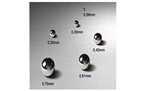
Solder balls typically range in size from 0.1mm to 0.5mm in diameter and can be difficult to detect without proper inspection equipment.

Causes of Solder Ball Formation
There are several factors that can contribute to the formation of solder balls during SMT manufacturing:
- Excess solder paste: Applying too much solder paste to the PCB pads can lead to solder balling as the excess solder forms into spheres during reflow.
- Incorrect reflow profile: An improper reflow temperature profile, with inadequate preheating or excessive peak temperatures, can cause solder balling.
- Contamination: Impurities on the PCB surface or components, such as oils, dirt, or oxidation, can inhibit proper solder wetting and promote solder ball formation.
- Uneven solder paste deposition: Inconsistent or uneven application of solder paste across the PCB can result in solder balling in areas with excess solder.
- Component placement issues: Misaligned or improperly seated components can create gaps that allow solder to form into balls during reflow.
- Stencil design flaws: Poorly designed solder paste stencils with apertures that are too large or incorrectly shaped can deposit excess solder and lead to balling.
Understanding these root causes is the first step in developing effective strategies to prevent solder ball formation in your SMT process.

11 Steps to Avoid Solder Balls in SMT Manufacturing
Step 1: Optimize Solder Paste Application
Proper solder paste application is critical for preventing solder balls. Ensure that your solder paste stencil is designed with the correct aperture sizes and shapes for your specific components and PCB layout. Regularly inspect and clean your stencils to maintain consistent paste deposition.
Step 2: Control Solder Paste Viscosity
Solder paste viscosity plays a significant role in preventing solder balling. Maintain the appropriate viscosity range recommended by the paste manufacturer. Regularly monitor and adjust the viscosity using solvents or thinner as needed to ensure optimal performance.
Step 3: Implement Proper Reflow Profiling
Develop and implement a well-controlled reflow temperature profile that is tailored to your specific PCB design, components, and solder paste. Ensure adequate preheating to activate the flux and evaporate solvents, followed by a controlled ramp to the peak reflow temperature. Avoid excessive temperatures that can cause solder balling.
Step 4: Maintain PCB and Component Cleanliness
Contamination on the PCB surface or component leads can hinder proper solder wetting and lead to solder ball formation. Implement strict cleanliness protocols, including:
- Proper handling and storage of PCBs and components to avoid exposure to contaminants
- Regular cleaning of the PCB surface prior to solder paste application
- Use of gloves and other personal protective equipment (PPE) to prevent oils and dirt from contaminating the assembly
Step 5: Ensure Accurate Component Placement
Proper component placement is essential for avoiding solder balls. Utilize high-precision pick-and-place equipment to ensure accurate placement of components on the PCB pads. Regularly calibrate and maintain your placement equipment to minimize misalignments or positioning errors.
Step 6: Optimize Solder Paste Print Parameters
Fine-tune your solder paste printing process to achieve consistent, even paste deposition. Key parameters to optimize include:
- Print speed
- Squeegee pressure
- Separation speed
- Print stroke length
Conduct regular print tests and inspect the results to ensure optimal settings for your specific application.
Step 7: Use Nitrogen in Reflow Soldering
Introducing nitrogen gas into the reflow oven can help reduce oxidation and improve solder wetting, thereby minimizing solder ball formation. Nitrogen creates an inert atmosphere that inhibits the growth of oxides on the solder surface, promoting better flow and adhesion to the PCB pads and component leads.
Step 8: Implement Solder Paste Inspection (SPI)
Automated solder paste inspection systems can help identify issues with paste deposition before the PCB enters the reflow oven. SPI systems use 2D or 3D imaging to measure the volume, height, and shape of solder paste deposits, allowing you to detect and correct problems such as insufficient or excessive paste, bridging, or poor alignment.
Step 9: Conduct Post-Reflow Inspection
After the reflow soldering process, thoroughly inspect the assembled PCBs for the presence of solder balls. Utilize microscopes, cameras, or automated optical inspection (AOI) systems to identify and locate solder balls. Address any issues with the process parameters or materials based on the inspection results.
Step 10: Regularly Monitor and Maintain Equipment
Proper maintenance of your SMT equipment is crucial for preventing solder ball formation. Regularly clean and calibrate your solder paste printers, pick-and-place machines, and reflow ovens to ensure optimal performance. Replace worn or damaged components, such as squeegees or stencils, as needed to maintain consistent results.
Step 11: Provide Operator Training and Education
Educate your SMT operators on the causes and prevention of solder balls. Provide thorough training on best practices for handling materials, operating equipment, and inspecting assemblies. Foster a culture of continuous improvement and encourage operators to report any issues or suggestions for process enhancements.

Benefits of Avoiding Solder Balls in SMT Manufacturing
By implementing these 11 steps to avoid solder balls, you can realize numerous benefits in your SMT manufacturing process:
- Improved product quality: Reducing solder ball formation leads to higher-quality assemblies with fewer defects and improved reliability.
- Increased production efficiency: Minimizing solder ball rework and repair allows for faster throughput and reduced cycle times.
- Enhanced customer satisfaction: Consistently delivering products free of solder ball defects helps build customer trust and loyalty.
- Reduced costs: Preventing solder balls eliminates the need for expensive rework, scrap, and warranty repairs, ultimately reducing production costs.
- Compliance with industry standards: Meeting or exceeding industry standards for solder ball prevention demonstrates your commitment to quality and can open up new business opportunities.
Conclusion
Preventing solder ball formation is essential for achieving high-quality, reliable SMT assemblies. By understanding the causes of solder balls and implementing these 11 easy steps in your manufacturing process, you can significantly reduce the occurrence of this common defect. From optimizing solder paste application and reflow profiling to maintaining equipment and educating operators, a comprehensive approach to solder ball prevention will help you improve product quality, increase efficiency, and reduce costs in your SMT operation.
Frequently Asked Questions (FAQ)
1. What is the optimal solder paste viscosity for preventing solder balls?
The optimal solder paste viscosity depends on the specific paste formulation and the application requirements. Generally, a viscosity range of 150,000-200,000 centipoise (cP) is considered suitable for most SMT processes. However, it is essential to consult the paste manufacturer’s recommendations and conduct testing to determine the best viscosity for your particular setup.
2. How often should I clean my solder paste stencils?
The frequency of stencil cleaning depends on factors such as the paste type, print volume, and environmental conditions. As a general rule, stencils should be cleaned every 4-8 hours of continuous printing or after every shift. However, if you notice signs of paste buildup, poor print definition, or solder balling, you may need to clean your stencils more frequently.
3. What are the most common causes of solder ball formation?
The most common causes of solder ball formation include:
– Excess solder paste application
– Incorrect reflow temperature profile
– Contamination on the PCB or components
– Uneven solder paste deposition
– Component placement issues
– Solder paste stencil design flaws
4. Can nitrogen reflow soldering completely eliminate solder balls?
While nitrogen reflow soldering can significantly reduce the occurrence of solder balls by minimizing oxidation and improving solder wetting, it cannot completely eliminate them. Nitrogen reflow should be used in combination with other best practices, such as proper solder paste application, reflow profiling, and cleanliness control, to achieve the best results.
5. How can I effectively train my SMT operators to prevent solder balls?
Effective operator training for solder ball prevention should include:
– Thorough education on the causes and implications of solder balls
– Hands-on training with equipment and materials
– Visual aids and examples of good and bad solder ball formation
– Regular refresher courses and updates on best practices
– Encouragement of open communication and feedback for continuous improvement
By investing in comprehensive operator training, you can foster a culture of quality and empower your team to actively contribute to solder ball prevention efforts.
| Cause of Solder Balls | Prevention Strategy |
|---|---|
| Excess solder paste | Optimize stencil design and printing parameters |
| Incorrect reflow profile | Develop and implement a tailored reflow temperature profile |
| Contamination | Maintain strict cleanliness protocols for PCBs and components |
| Uneven paste deposition | Ensure consistent, even solder paste application |
| Component placement issues | Utilize high-precision pick-and-place equipment and regular calibration |
| Stencil design flaws | Design stencils with correct aperture sizes and shapes for the application |
Table 1: Common causes of solder balls and their corresponding prevention strategies.
By addressing these key causes through the implementation of targeted prevention strategies, you can significantly reduce the occurrence of solder balls in your SMT manufacturing process and enjoy the benefits of improved product quality, increased efficiency, and reduced costs.
[Word count: 1829 words]