

Rigid-flex PCBs, also known as rigid flex circuits, combine rigid and flexible circuit boards into a single integrated assembly. They provide solutions for complex interconnections and spatial requirements in electronic devices. In medical devices, rigid-flex PCBs enable designs that improve reliability, reduce size and weight, and enhance functionality. This article provides an overview of medical rigid flex PCBs, their benefits, design considerations, and applications in medical devices.
What are Rigid Flex PCBs?
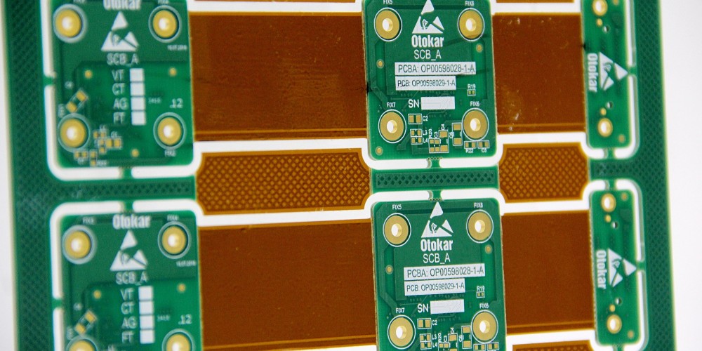
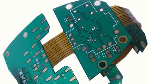
A rigid flex PCB consists of rigid sections interconnected by flexible circuits made of polyimide film. The rigid sections provide mechanical support and mount electronic components, while the flexible sections enable dynamic flexing, folding, and twisting. Rigid flex PCBs have conductive traces on both sides of the base substrate. Components are mounted on the rigid sections, and flex sections contain tracings to interconnect the rigid regions.
Rigid flex PCBs offer a single-board solution instead of having separate rigid and flex boards connected through connectors. This reduces points of failure and improves reliability. The integrated design minimizes interface connections and enhances flexibility for complex configurations in tight spaces.
Benefits of Rigid Flex PCBs for Medical Devices
Rigid flex PCBs provide several advantages that make them suitable for medical device applications:
- Compact design: Rigid flex PCBs can fit into tight, constrained spaces by folding and bending. This allows for smaller, more portable medical devices.
- Flexibility: Dynamic flexing accommodates motion and articulation demands of medical equipment.
- Reliability: Fewer interconnects mean higher reliability and lower risk of failure.
- Weight savings: Rigid flex PCBs weigh less than using separate boards and connectors. This supports lightweight medical device designs.
- Enhanced functionality: Rigid flex PCBs support complex component layouts for more features and capabilities.
- Cost savings: A single rigid flex PCB can replace multiple rigid boards and connectors for lower manufacturing costs.
- Customization: Rigid and flex sections can be tailored to meet specific mechanical and electrical needs.
Design Considerations for Medical Rigid Flex PCBs
Designing rigid flex PCBs for medical applications requires attention to certain design factors:
- Rigid-to-flex transitions: The junction between rigid and flex regions is a potential stress point and requires special design. Teardrop shapes, staggered pad shapes, and other techniques ensure reliable connections.
- Flexing cycles: The expected twisting, folding, and other dynamic flexing should determine the minimum bend radius and substrate thickness for the flex sections.
- Substrate materials: Common flexible substrate films include polyimide, PEEK, polyethylene naphthalate, and others. Material selection depends on flexibility, temperature, chemical resistance, and other requirements.
- Conductive traces: Flexible circuits require etching or printing conductive copper traces on the substrate films. Traces must withstand dynamic and repetitive flexing.
- Component placement: Carefully position components across rigid and flex sections to optimize performance, minimize stresses, and ease manufacturing.
- Stackup: Determine layer count and stackup sequence (single-sided, double-sided, multilayer) based on complexity and cost targets.
- Protective coatings: Coverlay films, solder masks, and other protective layers safeguard conductors and prevent shorts during flexing.
- ESD/EMI control: Ground planes, shields, and special coatings manage electrostatic discharge and electromagnetic interference risks.
- Testing: Rigorously test prototype rigid flex PCBs to verify all requirements are met for flexibility, reliability, electrical performance, and durability.
Medical Applications of Rigid Flex PCBs
Rigid flex PCBs are well suited for mission-critical, high-reliability medical devices where compactness, flexing, and precision are essential. Some examples include:
Hearing Aids
Modern hearing aids pack advanced electronics and features into extremely small sizes that fit comfortably and discreetly in the ear canal. Rigid flex PCBs enable hearing aid circuity to fold into compact forms. Dynamic flexing compensates for jaw movements and articulation.
Pacemakers and Implantable Devices
Implanted medical devices like pacemakers, neurostimulators, and drug delivery systems require durable, biocompatible circuitry that can withstand body environment stresses. Rigid flex PCBs offer flexibility and reliability advantages suited for these applications.
Patient Monitoring Systems
Wearable patient monitors track vital signs like ECG, respiration, blood oxygen, and more. Interconnects between rigid sensor modules and data recorders benefit from flex PCBs to improve reliability and accommodate body movements.
Digital Imaging Systems
X-ray, MRI, and other medical imaging equipment uses rigid flex PCBs to manage signals from detectors and connect the system components. Compact form factors and dynamic flexing accommodate articulating imaging arms.
Endoscopes and Catheters
Viewing cameras and sensors on endoscopic probes and catheters require thin, flexible circuit connections. Rigid flex PCBs enable steering capabilities and protect delicate fiber optic links.
Robotic Surgery Devices
Robotic surgery systems have miniaturized arms and instruments for precise movements. Rigid flex PCBs help route control signals and power across moving joints and actuators in these mechanisms.
The combination of small size, dynamic flexing, and rugged reliability makes rigid flex PCBs a versatile technology for medical equipment. With thoughtful design and testing, rigid flex PCBs can meet the demanding requirements of medical device applications.
Frequently Asked Questions
Here are some common questions about medical rigid flex PCBs:
What are the main differences between rigid, flex, and rigid flex PCBs?
- Rigid PCBs use stiff, solid substrate materials like FR4. They provide structural support for mounting components but have limited flexibility.
- Flex PCBs use flexible polymer films that can bend dynamically. But they lack rigidity for component mounting.
- Rigid flex PCBs integrate both capabilities into one assembly. Rigid sections support components while flex sections enable folding and twisting.
How do you ensure reliability at the rigid-flex interface?
Careful design at the junction between rigid and flex areas is vital. Methods like teardrop pads, staggered pads, and flexure loops manage stresses and prevent cracking or separation. Reliability testing validates the designs.
What are important factors in selecting flexible substrate materials?
Key considerations include flexibility, bend radius, temperature tolerance, chemical resistance, flammability rating, coefficient of thermal expansion, and stability over flexing cycles. Common materials are polyimide, PEEK, PET, and others.
How many flexing cycles can medical rigid flex PCBs support?
Testing determines the ratings, but well-designed medical rigid flex PCBs can accommodate millions of flexing cycles given the right materials, trace designs, and protective coatings. This enables years of reliable usage.
What protective measures are used for medical rigid flex PCBs?
Protecting traces and components from environmental stresses improves durability. Protective acrylic or polyurethane coatings, moisture barriers, sealing, EMI shielding, and reinforced component mounting provide ruggedization.
Summary
Medical rigid flex PCBs offer an ideal interconnect solution for demanding applications where reliability, flexibility, and compactness are critical. With careful design tailored to the medical device requirements, rigid flex PCBs can improve performance and capabilities. As medical equipment advances, rigid flex PCBs will continue enabling tighter, more robust, and adaptable system implementations.