


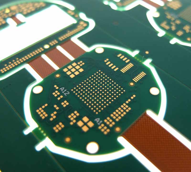
Rigid-flex printed circuit boards (PCBs) combine rigid and flexible circuitry into a single component, providing more design flexibility compared to traditional rigid PCBs. However, rigid-flex PCBs also come with some drawbacks that designers should consider.
Higher cost
One of the main disadvantages of rigid-flex PCBs is their higher cost compared to rigid PCBs. There are several reasons for the increased costs:
More complex manufacturing
Rigid-flex PCB fabrication requires more steps, specialized materials, and careful handling compared to standard rigid PCBs. The flexible layers need to be laminated with alternating layers of rigid fiberglass at high heat and pressure. This complex process requires specialized equipment and results in lower manufacturing yields.
More expensive materials
The flexible substrate material, typically polyimide, costs more than the FR-4 fiberglass used for rigid PCBs. The adhesive used to bond the layers together is also more expensive than standard PCB lamination.
Lower volume production
Rigid-flex PCB production volumes are lower compared to rigid PCBs. The increased costs are amortized over fewer boards, resulting in higher per-unit pricing.
According to industry sources, rigid-flex PCBs typically cost at least twice as much as equivalent rigid boards. For example, a 6-layer rigid board may cost $1500 whereas a 6-layer rigid-flex may cost $3000. The costs increase further as the number of layers increases.
Design challenges
Rigid-flex PCBs require special design considerations, especially at the junction between rigid and flex sections. Here are some of the key design challenges:
Flex-rigid transition
The mechanical transition from a rigid section to a flexible section requires careful analysis. The board needs to bend smoothly without damaging traces or pads. Typically, teardrop shapes and other rounded structures are used to reduce stress concentrations.
Matching coefficients of thermal expansion
The different expansion coefficients of the rigid and flex materials can induce stresses during temperature changes. The design needs to account for these mismatches to avoid issues like delamination or cracked traces.
Reduced routing space
Vias and traces need to be set back from the edges of the rigid sections that transition to flex areas. This “keepout” region reduces the available routing space.
Capturing flex area
The flexible sections need to be held down, often requiring additional stiffener layers or adhesive patches. This captured area also reduces usable space for traces and components.
Limited flex cycles
While the flexible layers in rigid-flex boards provide more durability than bare wires, they still have a finite flex life. The repeated bending leads to trace fractures and material fatigue over time.
The number of flex cycles varies based on trace thickness, substrate material, bend radius, and other factors. Typical values range from a few thousand cycles for sharp bends to over 100,000 cycles for gradual bends.
To avoid field failures, engineers have to model the expected use conditions and ensure the design remains within the allowable flex cycles. The limited flex life makes rigid-flex PCBs unsuitable for applications requiring continual motion.
More prone to damage
Rigid-flex boards are inherently more prone to handling damage compared to rigid boards. The thin, exposed flexible layers and joints between sections provide opportunities for damage.
Problems can occur during:
- PCB fabrication – Additional handling steps increase chances of unexpected creases, folds or tears
- Component assembly – Improper support below flex areas may cause damage during soldering or placement
- Product assembly – Incorrect bending or routing can rip traces at the transitions
- Field use – End users may flex the boards beyond allowable radii, damaging traces
Each handling stage requires awareness of the rigid-flex structure to prevent damage. The relative fragility factors into the overall design tradeoffs.
Higher level of expertise required
Designing and manufacturing rigid-flex PCBs requires specialized expertise across the supply chain. Here are some examples of the higher skill levels needed:
- PCB designers need training on rigid-flex design practices to account for flex, thermal, and mechanical factors.
- PCB fabricators require expertise on the materials, processes, and handling to achieve robust rigid-flex boards.
- Assemblers need to select compatible components and adhesives, and adjust processes to avoid damaging flex areas.
- Product assemblers require training on proper techniques for routing and installing rigid-flex boards.
The expertise requirements increase costs and reduce the pool of qualified vendors. Companies new to rigid-flex may encounter difficulties finding the right design consultants and manufacturing partners.
Longer lead times
The additional fabrication and assembly considerations for rigid-flex PCBs lead to increased manufacturing lead times.
According to industry data, typical lead times are:
| PCB Type | Lead Time |
|---|---|
| Rigid PCB | 5-15 days |
| Rigid-Flex PCB | 15-25 days |
The longer lead times must be factored into product development schedules. Last minute design changes are particularly problematic with rigid-flex boards, as small tweaks can require complete board respins.
Difficult rework and repairs
Reworking errors and repairing damage is more difficult with rigid-flex PCBs compared to rigid boards.
Issues include:
- Limited access – Components may be mounted on the rigid sections while interconnected traces run through the flex areas. This makes it difficult to reach and replace faulty components.
- Desoldering challenges – Applying heat for desoldering risks damaging the flexible layers. Special FPC connectors may be required to avoid this.
- Trace repairs – Damaged traces in the flex area can’t be easily patched. Often the entire layer needs replacing.
- Section replacements – A damaged flex section may necessitate replacing the entire rigid-flex assembly.
For critical products, designers may need to create separate testable sub-assemblies to enable modular replacements. This further increases design time and cost.
Summary of disadvantages
The key disadvantages of rigid-flex PCBs include:
- Higher fabrication and materials cost
- More complex designs
- Limits on flex cycles
- Increased fragility
- Need for specialized expertise
- Longer lead times
- Difficult rework and repairs
These downsides must be weighed against the advantages like simplified interconnects, improved reliability, and more efficient use of space. Rigid-flex PCBs provide benefits for many applications but aren’t suitable for cost-sensitive or high volume products.
Frequently Asked Questions
Here are some common questions about the disadvantages of rigid-flex PCBs:
Q: Are rigid-flex PCBs only for complex or advanced designs?
A: In the past, rigid-flex PCBs were associated with advanced aerospace and military products. But modern design tools along with improving fabrication capabilities have made rigid-flex a viable option even for less complex consumer devices. The higher costs may still limit use in price-sensitive products however.
Q: Can’t you split a rigid-flex into separate rigid and flex boards to reduce cost?
A: In theory yes, a monolithic rigid-flex board could be divided into discrete rigid and flex boards interconnected with cables or connectors. However, this defeats many of the advantages of a unified rigid-flex design and introduces reliability risks from the interconnects. Rigid-flex PCBs are best suited for products that benefit from seamless integration of the rigid and flex sections.
Q: How many flex cycles are needed in typical rigid-flex applications?
A: Most consumer and industrial applications require less than 10,000 flex cycles over the product lifetime. Applications with continual flexing may need up to 100,000 cycles. Extreme folded flexing reduces the cycle count further. Careful modeling of the expected use conditions determines the required flex cycle rating.
Q: Can repairs be made by replacing damaged flex layers only?
A: Selectively replacing only the damaged flex layers is difficult, as the layers are tightly bonded to the rigid sections. It may be possible for boards with more than 4-5 layers, but often the entire rigid-flex assembly needs replacing. Modular sub-assembly design can improve repairability.
Q: Are there any newer technologies to reduce rigid-flex PCB costs?
A: Some newer techniques like molded interconnect devices (MIDs) can integrate rigid and flex sections via injection molding rather than lamination. This reduces layer count and cost, but design complexity increases. Polymer thick film flex layers are also an emerging lower-cost technology. In general however, rigid-flex PCBs will remain more expensive than rigid PCBs.