What is a Flexible PCB Board?
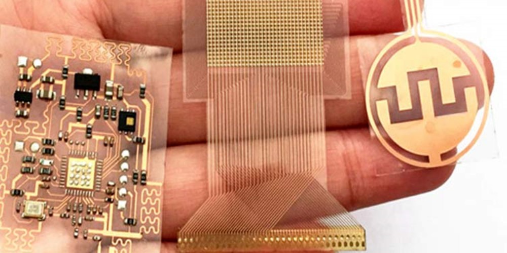
A flexible printed circuit board (flex PCB or flex circuit) is a type of printed circuit board made of flexible insulating substrate material such as polyimide or polyester. The conductive pathways are printed or bonded onto the flexible substrate. Flex PCBs allow for dynamic flexing, vibration dampening, and installation around irregular shapes. They are commonly used in consumer electronics, medical devices, industrial electronics, and automotive applications.
Benefits of Flexible PCBs
Here are some of the key benefits of using flexible PCBs:
- Dynamic flexing – Flex circuits can bend and flex repeatedly without damage. This makes them well-suited for applications involving motion and vibration.
- Lightweight – Flex PCBs use thin flexible substrate materials, making them much lighter than traditional rigid PCBs. Weight reduction is important in many applications.
- Thin and customizable shapes – Flex circuits can be fabricated in thin, customized outlines. They can fit into tight spaces and odd form factors where rigid boards would be difficult.
- Stress relief – The dynamic flexing of a flex PCB acts as a stress reliever. This improves reliability and product life compared to a rigid-flex interface.
- Scalable production – Flex PCBs allow for efficient large volume production using roll-to-roll processing.
- Design freedom – Circuits can be distributed across multiple interconnected flex layers, allowing for greater functionality in a small space.
Types of Flexible PCBs
There are several design variants of flex PCBs, including:
- Single-sided flex – Conductive layers on only one side of the substrate.
- Double-sided flex – Conductive layers on both sides. Provides more interconnects than a single-sided flex.
- Multi-layer flex – Flex boards with three or more conductive layers, allowing for greater circuit complexity.
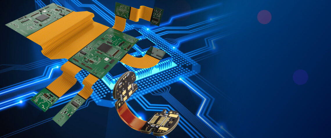
- Rigid-flex – Combines rigid PCB sections with flexible PCB sections, joined by a flexible bend area. Provides structural support while still allowing dynamic flexing.
- Flexible rigid – A rigid PCB with a section cut out and replaced by a flexible circuit. The rigid board provides the mount and structure.
Flexible PCB Material and Construction
Flexible PCBs are made up of flexible insulating substrate materials that provide the base. On top of the substrate are stacked alternating layers of conductive copper and insulating dielectric materials.
Substrate Materials
Common substrate materials used in flex PCB fabrication include:
- Polyimide (PI) – Most common flex PCB substrate. Provides excellent thermal stability and chemical resistance. Brand names include Kapton and Apical.
- Polyester (PET) – Lower cost alternative with moderately good thermal and chemical stability. Common brand name is Mylar.
- Polyethylene Naphthalate (PEN) – High performance polyester with improved thermal and mechanical properties over PET. Sold as Teonex or Q65.
- Polyethylene Terephthalate (PET) – Another lower cost flexible substrate option. Provides good chemical resistance.
Layers
A basic flex PCB consists of a flexible substrate layer with a single layer of copper traces on one or both sides. More complex flex circuits can have multiple conductive layers separated by dielectric insulation layers.
Typical layer stackup:
- Flexible substrate (polyimide, PET)
- Adhesive bonding layer
- Copper conductive layer
- Dielectric insulation layer
- Copper conductive layer
- Coverlay insulation
The number of layers can range from 1 to over 15 for the most complex flex PCB designs.
Flex PCB Design Considerations
Designing a reliable, manufacturable flex PCB requires considering factors such as:
Flexibility
The flexural stiffness of the PCB must be low enough for the required dynamic bending, while still providing enough support. Polyimide substrates provide excellent flexural properties.
Conductor Spacing
Conductor lines and spaces must be designed to account for flexing stresses. Typical line/space is 2 mil (0.05mm) or greater.
Layer Stacking
Carefully arrange conductor layers to avoid shorts and crosstalk during flexing. Adhesives must also withstand flexing.
Bend Radius
A minimum bend radius based on the board thickness avoids damage like folding and creasing. Typical minimum is 10X the total board thickness.
Stiffeners
Strategically placed stiffeners made of thicker substrate or laminate materials can be added to aid in insertion or connection.
Reinforcement
Areas expected to endure frequent flexing should include coverlay or additional laminate layers as reinforcement.
Flex PCB Manufacturing Process

Flex PCB fabrication involves specialized processes tuned for flexible substrates. Here is a general outline:
- Design creation with CAD software
- Photolithography artwork generation
- Substrate cleaning and surface preparation
- Photoresist lamination
- Imaging conductive layers
- Etching to form circuit traces
- Stripping of photoresist
- Lamination of dielectric and adhesive layers
- Drilling of mounting holes
- Plating of conductive vias and barrels
- Solder mask application
- Silkscreen printing of markings
- Electrical testing
- Singulation into individual PCBs
Rigid-flex boards require additional steps to bond the rigid and flex materials.
Flex PCB Assembly
Assembling components onto flex PCBs also requires some unique considerations:
Soldering
Reflow soldering must be done at lower temperatures to avoid damage to flex boards. Soldering iron temperature and time must be controlled.
Component Securing
Adhesives are often used to securely attach components to flex PCBs, avoiding vibration and shock failure.
Connectors
Zero insertion force (ZIF) connectors allow easy mating without applying stress to flex circuit conductors. Flex connectors are also available.
Harnesses
Ribbon cables or specialty flex jumpers are used to interconnect rigid and flex sections of a design.
Flex PCB Applications
Some examples of products that use flexible PCB technology:
- Wearable devices
- Medical electronics
- Mobile phones
- Tablets and laptops
- Cameras
- Automotive electronics
- Industrial sensors and controls
- IoT edge nodes
Any application requiring a thin, lightweight and dynamically flexing circuitry can benefit from flexible PCB technology. The range of applications will continue expanding as flex PCBs become more advanced and cost effective.
Flex PCB vs Rigid PCB Comparison
Flex PCB Advantages:
- Thinner, lighter, and more customizable form factors
- Dynamic flexibility and vibration damping
- Improved reliability with flexing motion
- Design freedom with flex layer interconnects
- Efficient roll-to-roll manufacturing techniques
Rigid PCB Advantages:
- More structural rigidity and component support
- Easier assembly with standard components
- Often lower costs in low quantities
- Well established manufacturing processes
- Can achieve very high circuit density
FQA About Flexible PCB Boards
Here are answers to some frequently asked questions about flex PCB technology:
What are the typical substrate thicknesses used in flex PCBs?
Polyimide is commonly available in 12.5μm, 25μm, 50μm, and 75μm thicknesses. PET substrates range from 13μm to 250μm. Thicker substrates provide more support while thinner ones allow tighter bend radii.
What are common dielectric insulation materials used in multilayer flex boards?
Popular dielectric insulation films include polyimide, PET, acrylic, and epoxy blends. Dielectric constant ranges from 3.0 to 4.5. Thickness is typically around 25μm.
What is the typical minimum bend radius for a flex PCB?
The minimum bend radius is usually described as a multiple of total board thickness. A common guideline is a minimum bend radius of 10 times the total flex PCB thickness. With thinner boards this enables very tight folds.
What are effective ways to reduce costs when designing a flex PCB?
Strategies like minimizing the number of conductive layers, using fewer bending sections, standardizing on component footprints, and relaxing tolerances can help reduce flex PCB costs.
What are some key considerations when selecting connectors for flex PCBs?
Look for flex-tail compatible connectors with smooth entries designed to avoid damaging conductors. Zero insertion force (ZIF) and other flexible interconnect solutions make mating easier.


