

Introduction to Rigid-Flex PCBs
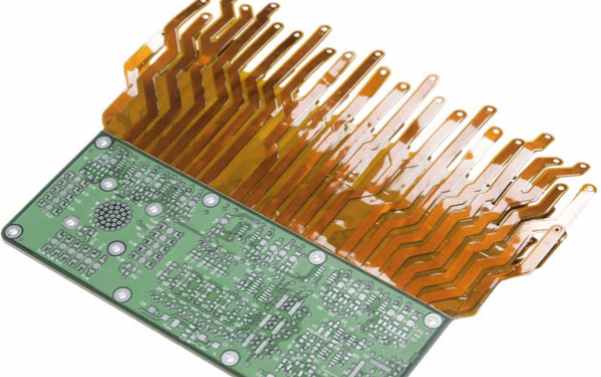
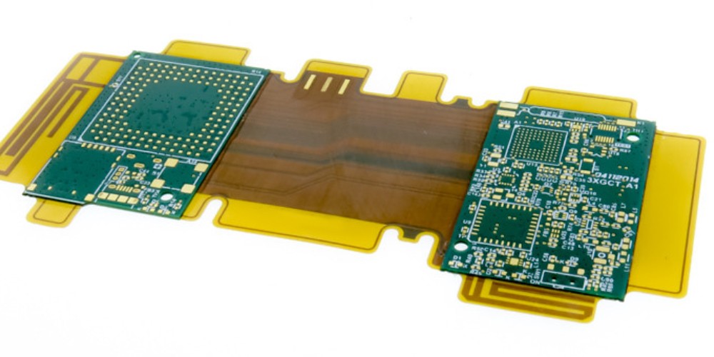
Rigid-flex PCBs, also known as flex-rigid PCBs, are circuit boards that consist of rigid and flexible substrates laminated together into a single structure. The rigid sections provide stability while the flexible sections allow dynamic flexing and bending. This combination offers numerous advantages over rigid PCBs or flexible PCBs alone.
Rigid-flex PCBs first emerged in the 1960s for aerospace applications. Today they are used extensively in a variety of industries including automotive, telecommunications, industrial, and especially consumer electronics. Common applications include cell phones, laptops, cameras, and wearable devices.
What is a Rigid-Flex PCB?
A rigid-flex PCB combines rigid substrates (usually FR-4 fiberglass) with flexible substrates such as polyimide or PEEK. The flexible materials act as “hinges” between the rigid regions. Vias and traces can pass from the rigid sections to the flexible sections. Components are typically mounted on the rigid portions only.
Rigid-flex PCBs fall into three categories:
- Rigid-Flex: Contains both rigid and flex sections.
- Flex-Rigid: Dominated by flexible substrate with isolated rigid sections.
- Rigid-Flex-Rigid: Combines multiple rigid and flex layers.
Manufacturing Rigid-Flex PCBs
Rigid-flex PCBs require specialized manufacturing. First, the rigid and flexible materials are laminated together. The board then goes through lithography and etching to form the traces and pads. Vias are drilled and plated to connect between layers. Components are soldered on the rigid portions.
Benefits of Using Rigid-Flex PCBs
Here are some of the major benefits of rigid-flex PCBs compared to rigid PCBs:
Dynamic Flexibility
The flexible sections of rigid-flex PCBs allow for dynamic flexing and bending of the board. This is critical for devices that need to bend and flex during use, such as laptops and mobile phones. The rigid portions provide stability and component mounting while the flex portions accommodate movement and twisting.
Reduced Weight and Size
By eliminating connectors between rigid PCBs, rigid-flex PCBs greatly reduce the total weight and size of electronic packages. This lightweight profile allows for smaller, sleeker product designs. Weight and size reduction are especially noticeable in portable consumer devices.
Enhanced Reliability
Eliminating connectors and solder joints increases reliability. Connectors are prone to failure over time from use and vibration. Rigid-flex PCBs have fewer failure points with continuous connections between rigid sections.
Increased Layer Counts
Rigid-flex PCBs enable far greater total board layer counts by integrating multiple rigid layers and flex layers. More layers provide higher component density and accommodate complex circuitry.
Improved Signal Speed
The continuous connections between rigid sections allow for higher speed signals without losses through connectors. Shorter uninterrupted traces also increase signal speeds. This boosts performance in high frequency applications.
Lower Assembly Costs
By reducing component count and manual assembly steps, rigid-flex PCBs lower overall system assembly costs. Automated assembly steps also replace manual connector assembly.
Design Flexibility
Rigid-flex PCBs enable more creative industrial design of electronics. Dynamic flexing and bending allows for packaging innovation not possible with rigid PCBs. Devices can be designed around the human body with rigid-flex PCBs.
Reduced System Complexity
Rigid-flex PCBs integrate interconnections into the circuit board, eliminating the need for separate wires and connectors. This reduces design complexity, part count, and system assembly time.
Improved Thermal Performance
The thinner flex sections reduce thermal resistance and allow for better thermal dissipation than electrical connectors. Heat can transfer between rigid sections through the flexible segments.
Applications of Rigid-Flex PCBs
Rigid-flex PCBs are used in a wide array of industries and applications including:
Consumer Electronics
- Mobile phones
- Laptops
- Tablets
- Digital cameras
- Wearable devices
Automotive Electronics
- Navigation and entertainment systems
- Driver information clusters
- Advanced driver assistance systems
- Hybrid and electric vehicle control systems
Industrial Electronics
- Robotics
- Factory automation equipment
- Industrial internet of things (IIoT) devices
Medical Electronics
- Imaging systems
- Patient monitoring equipment
- Implantable devices
- Wearable health trackers
Military and Aerospace
- Aircraft control systems
- Satellite systems
- Missile guidance systems
- Avionics
Rigid-Flex PCB Design Considerations
Designing a successful rigid-flex PCB requires considering a number of factors:
Layer Stackup
The designer must plan the layer stackup, determining the number and sequence of rigid and flex layers needed. This impacts flexibility, rigidity, and component placement.
Conductor Routing
Traces must be routed between rigid sections through the flexible layers. Controlled impedance traces may require planning.
Component Placement
Components can only be placed on rigid portions of the PCB. Their placement must not restrict planned flexible zones.
Flex Bending Radius
The bending radius of flex areas must be within material limits to avoid cracking or fouling. Typical minimum bend radius is 3-10 times material thickness.
Flex-to-Rigid Transition
Special consideration is required where traces transition between the rigid and flex sections. Appropriate conductor widths and materials must be used.
Thermal Management
Thermal dissipation and heating effects must be considered especially for high power components on the rigid sections.
Manufacturing Capabilities
The design should account for manufacturing capabilities of the PCB vendor. This includes minimum spacing, traces, drill sizes, and more.
Testing and Inspection
The quality process must test both rigid and flex sections. Automated optical inspection (AOI) and x-ray are commonly used.
Rigid-Flex PCB Materials
There are a wide variety of rigid and flexible materials that can be combined into a rigid-flex PCB.
Rigid Substrate Materials
- FR-4 Glass Epoxy – Most common rigid PCB material
- FR-5 High Tg Glass Epoxy – For high temperature applications
- CEM-1 Cotton Epoxy – Cost effective option
- Polyimide – Extremely heat resistant
- Aluminum – For high thermal conductivity
Flexible Substrate Materials
- Polyimide – Most common flex material
- PEEK – For high temperatures
- Polyester – Cost effective material
- PET – Polyethylene Terephthalate
- Polyurethane – Extreme flexibility
Bonded Layers
- Acrylic – Most common rigid-flex bonding adhesive
- Epoxy
- Nitrile Phenolic – High chemical resistance
Rigid-Flex PCB Design Tools
Successfully designing a rigid-flex PCB requires specialized design tools. Key features needed in a rigid-flex PCB design system include:
- Multiple-stage design – create the rigid sections and flexible layers independently
- 2D/3D visualization – easily visualize the 3D board for analysis
- Flexible routing – interactively route traces between rigid sections
- Dynamic flex showing – dynamically model, animate, and analyze flexing
- DfM checks – validate manufacturability of rigid and flex areas
- Documentation tools – facilitate generating comprehensive fabrication notes
Most major PCB design systems today like Cadence Allegro, Mentor Xpedition, and Altium Designer have extensive rigid-flex design capabilities integrated.
Rigid-Flex PCB Fabrication and Assembly
Producing reliable and robust rigid-flex PCBs requires an experienced flex PCB manufacturer with specialized capabilities:
- Handling thin flexible materials down to 25 microns
- Photolithography and etching processes for fine features
- Drilling microvias for any layer-to-layer connections
- Surface finishes resistant to repeated flexing
- Solder mask and legend printing on flex
- Comprehensive QA testing of both rigid and flex
- masslam and adhesive containment routing
- Flex-to-rigid transition design support
- High mix/low volume and quick-turn production
In assembly, components are typically placed only on the rigid portions of the board. Standard SMT assembly is used. The dynamic flexible areas are left empty.
Future Outlook for Rigid-Flex PCBs
The rigid-flex PCB market has enjoyed strong growth over the past decade thanks to rising adoption in consumer electronics and automotive applications. One forecast predicts the global rigid-flex PCB market will grow from $3.49 billion in 2021 to $7.91 billion by 2028, an impressive CAGR of 12.5%.
Several trends are driving growth in rigid-flex PCB demand:
Miniaturization – Continued customer demand for smaller, slimmer, lighter portable electronic devices.
High Speed – Need for improved signal speed and integrity in applications like 5G communications.
Complexity – Integrating more functionality drives adoption of multilayer rigid-flex PCBs.
Automotive Use – Rigid-flex PCBs support automotive applications from driver displays to ADAS sensors.
Medical Devices – Healthcare applications from imaging systems to implants benefit from rigid flex PCBs.
Rigid-flex PCB technology will continue advancing with new materials, fabrication methods, and design tools. The growth opportunities are tremendous thanks to the many benefits rigid-flex PCBs offer in electrical system interconnectivity, reliability, and flexibility compared to traditional PCB technologies.
Frequently Asked Questions
What are some key benefits of using rigid-flex PCBs?
Some major benefits of rigid-flex PCBs include dynamic flexibility, reduced size and weight, improved reliability, design flexibility, and higher layer counts. The combination of rigid and flex materials provides an ideal interconnect solution for many applications that need both stability and dynamic bending capability.
Are components mounted on both the rigid and flex portions?
Typically components are only mounted on the rigid portions of a rigid-flex PCB. The flexible areas are left bare to accommodate bending and flexing motion. Conductors can freely pass between the rigid and flex areas.
What industries make the most use of rigid-flex PCBs?
Rigid-flex PCBs see heavy use in consumer electronics (phones, tablets, laptops), automotive (infotainment, instrumentation), industrial (robotics, automation), and medical (imaging, implants) applications. The aerospace industry was an early adopter as well.
Can rigid-flex PCBs be single or double sided?
Yes, rigid-flex PCBs can be designed as single sided or double sided. However, multilayer rigid-flex PCBs with 4 or more layers are much more common, as multiple rigid and flex layers are combined into a single package.
How small can flex layer thickness be made?
Rigid-flex PCBs can have flexible layers as thin as 25 microns, though 50 microns is more common. Rigid layers are typically 100 microns and higher. Excessively thin flex layers can present fabrication challenges and reliability risks.