

Introduction to Rigid-Flex PCBs
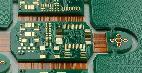
Rigid-Flex PCBs are a unique type of printed circuit board that combines the best features of both rigid and flexible circuits. These boards consist of multiple layers of flexible and rigid substrates that are laminated together to form a single, unified structure. This innovative design allows for greater flexibility, reliability, and space savings compared to traditional rigid PCBs.
Rigid-Flex PCBs have become increasingly popular in various industries, including aerospace, medical devices, automotive, and consumer electronics. They offer numerous advantages, such as reduced weight and size, improved signal integrity, and enhanced mechanical stability. As a result, more and more manufacturers are turning to Rigid-Flex PCBs to meet the demands of modern electronic devices.
Advantages of Rigid-Flex PCBs
- Space Savings: Rigid-Flex PCBs allow for more compact designs by eliminating the need for connectors and cables between separate rigid and flexible boards.
- Increased Reliability: With fewer interconnects and a unified structure, Rigid-Flex PCBs offer improved reliability and reduced risk of connection failures.
- Enhanced Signal Integrity: The reduced number of interconnects and shorter signal paths in Rigid-Flex PCBs minimize signal loss and interference.
- Improved Mechanical Stability: The combination of rigid and flexible substrates provides better mechanical support and reduces stress on components.
- Weight Reduction: Rigid-Flex PCBs eliminate the need for additional connectors and cables, resulting in overall weight reduction.
Layers in Rigid-Flex PCBs
Rigid-Flex PCBs can be manufactured with varying numbers of layers, typically ranging from 2 to 30 layers. The number of layers depends on the complexity of the design and the specific requirements of the application. Each layer serves a specific purpose and contributes to the overall functionality of the board.
Types of Layers in Rigid-Flex PCBs
- Conductive Layers: These layers are made of copper and are responsible for carrying electrical signals throughout the board. They can be either rigid or flexible.
- Insulating Layers: Insulating layers, also known as dielectric layers, provide electrical isolation between conductive layers. They are typically made of materials such as polyimide or FR-4.
- Adhesive Layers: Adhesive layers are used to bond the conductive and insulating layers together, ensuring a strong and reliable connection.
- Coverlay Layers: Coverlay layers are applied to the outer surfaces of the flexible portions of the board to protect the circuitry from damage and environmental factors.
Common Layer Configurations
| Layers | Configuration | Application |
|---|---|---|
| 2 | 1 Rigid + 1 Flex | Simple, low-cost designs |
| 4 | 2 Rigid + 2 Flex | Moderate complexity, improved signal integrity |
| 6 | 3 Rigid + 3 Flex | Complex designs, high-density routing |
| 8+ | Multiple Rigid + Multiple Flex | High-end applications, advanced packaging |
Design Considerations for Rigid-Flex PCBs
Designing Rigid-Flex PCBs requires careful consideration of various factors to ensure optimal performance and manufacturability. Some key design considerations include:
Bend Radius and Flexibility
The bend radius is a critical factor in Rigid-Flex PCB design, as it determines the minimum radius at which the flexible portions of the board can be bent without causing damage. The bend radius is typically specified by the manufacturer and depends on the thickness and material properties of the flexible layers.
To ensure reliable operation, designers must adhere to the recommended bend radius and avoid sharp bends or folds in the flexible regions. Additionally, it is essential to consider the number of flex cycles the board will experience over its lifetime and design accordingly.
Material Selection
Choosing the right materials for Rigid-Flex PCBs is crucial for achieving the desired performance and reliability. The most common materials used for the rigid portions of the board are FR-4 and polyimide, while the flexible portions typically use polyimide or other flexible substrates.
When selecting materials, designers must consider factors such as the dielectric constant, thermal stability, and mechanical properties to ensure compatibility with the application requirements. It is also essential to work closely with the manufacturer to select materials that are suitable for the specific manufacturing process.
Via Placement and Routing
Proper via placement and routing are critical for maintaining signal integrity and reliability in Rigid-Flex PCBs. Vias should be placed strategically to minimize the length of signal paths and reduce the risk of signal degradation.
In the flexible regions of the board, it is essential to use tear-drop shaped pads for vias to reduce stress concentration and improve mechanical stability. Additionally, designers should avoid placing vias in areas that will experience high stress or repeated bending to prevent via cracking or delamination.
Stiffener Placement
Stiffeners are used in Rigid-Flex PCBs to provide additional mechanical support and reduce stress on components in the rigid portions of the board. Stiffeners are typically made of materials such as FR-4 or aluminum and are bonded to the rigid layers of the board.
When placing stiffeners, designers must consider the location of components and the overall mechanical requirements of the board. Stiffeners should be placed in areas that require additional support, such as around connectors or heavy components, while avoiding interference with the flexible regions of the board.

Manufacturing Process for Rigid-Flex PCBs
The manufacturing process for Rigid-Flex PCBs is more complex compared to traditional rigid PCBs due to the combination of rigid and flexible materials. The process typically involves the following steps:
- Material Preparation: The rigid and flexible substrates are prepared by cutting them to the required sizes and shapes.
- Lamination: The rigid and flexible layers are laminated together using adhesive layers under high temperature and pressure.
- Drilling: Holes are drilled through the laminated board for vias and component mounting.
- Plating: The drilled holes are plated with copper to create electrical connections between layers.
- Patterning: The desired circuit patterns are transferred onto the board using photolithography and etching processes.
- Solder Mask Application: A solder mask is applied to the board to protect the circuitry and prevent short circuits.
- Surface Finishing: The exposed copper areas are coated with a protective finish, such as ENIG (Electroless Nickel Immersion Gold) or HASL (Hot Air Solder Leveling).
- Cutting and Routing: The board is cut and routed to the final shape and size, with the flexible regions being separated from the rigid portions.
- Testing and Inspection: The completed Rigid-Flex PCB undergoes thorough testing and inspection to ensure quality and functionality.

Applications of Rigid-Flex PCBs
Rigid-Flex PCBs find applications in various industries where space constraints, reliability, and flexibility are critical. Some common applications include:
Aerospace and Defense
In aerospace and defense applications, Rigid-Flex PCBs are used in avionics systems, satellites, and military equipment. These boards offer high reliability, resistance to vibration and shock, and the ability to withstand extreme temperatures and environmental conditions.
Medical Devices
Rigid-Flex PCBs are extensively used in medical devices, such as wearable monitors, implantable devices, and surgical instruments. The flexibility and compact size of these boards allow for the development of smaller, more comfortable, and less invasive medical devices.
Automotive Electronics
In the automotive industry, Rigid-Flex PCBs are used in various applications, including infotainment systems, driver assistance systems, and electronic control units. These boards offer reliable performance in the harsh automotive environment, withstanding vibration, temperature fluctuations, and moisture.
Consumer Electronics
Rigid-Flex PCBs are increasingly used in consumer electronics, such as smartphones, tablets, and wearable devices. The compact size and flexibility of these boards enable the development of sleek, lightweight, and feature-rich devices that meet consumer demands.
Choosing a Rigid-Flex PCB Manufacturer
When selecting a Rigid-Flex PCB manufacturer, it is essential to consider several factors to ensure high-quality boards that meet your specific requirements. Some key considerations include:
Experience and Expertise
Choose a manufacturer with extensive experience in producing Rigid-Flex PCBs and a proven track record of delivering high-quality boards. Look for manufacturers who have expertise in working with a wide range of materials, layer configurations, and manufacturing processes.
Quality Control and Certifications
Ensure that the manufacturer has a robust quality control system in place and holds relevant certifications, such as ISO 9001, ISO 14001, and UL Certification. These certifications demonstrate the manufacturer’s commitment to quality, reliability, and environmental responsibility.
Technical Support and Design Assistance
Select a manufacturer that offers comprehensive technical support and design assistance to help optimize your Rigid-Flex PCB design for manufacturability and performance. The manufacturer should have a knowledgeable team of engineers who can provide guidance on material selection, layer configuration, and design rule compliance.
Manufacturing Capabilities and Capacity
Consider the manufacturer’s manufacturing capabilities and capacity to ensure they can meet your production requirements. Look for manufacturers with state-of-the-art equipment, automated processes, and the ability to handle a wide range of layer counts and board sizes.
Lead Time and Pricing
Evaluate the manufacturer’s lead times and pricing structure to ensure they align with your project timeline and budget. Keep in mind that while cost is an important factor, it should not be the sole determining factor when choosing a Rigid-Flex PCB manufacturer. Quality, reliability, and technical expertise should also be given due consideration.
Frequently Asked Questions (FAQ)
-
What is the minimum bend radius for Rigid-Flex PCBs?
The minimum bend radius for Rigid-Flex PCBs depends on the thickness and material properties of the flexible layers. Typically, the minimum bend radius is 6-10 times the thickness of the flexible portion of the board. It is essential to consult with the manufacturer to determine the specific bend radius requirements for your design. -
Can Rigid-Flex PCBs be reworked or repaired?
Reworking or repairing Rigid-Flex PCBs can be challenging due to the complexity of the board structure and the presence of both rigid and flexible materials. While it is possible to perform minor repairs, such as replacing components or repairing damaged traces, extensive rework or repair may not be feasible. It is essential to work with experienced technicians and follow proper procedures to minimize the risk of further damage to the board. -
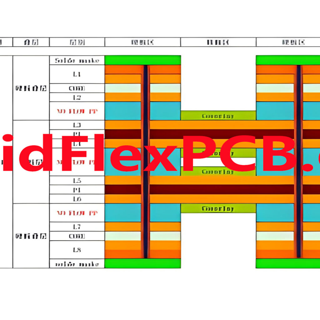
How do I specify the layer stackup for a Rigid-Flex PCB?
When specifying the layer stackup for a Rigid-Flex PCB, it is essential to provide detailed information about the number and type of layers required, the thickness of each layer, and the material preferences. Work closely with the manufacturer to ensure that the layer stackup meets your design requirements and is compatible with their manufacturing process. Provide clear illustrations or diagrams of the desired layer configuration to avoid any confusion or misinterpretation. -
What are the common challenges in Rigid-Flex PCB Assembly?
Rigid-Flex PCB assembly presents several challenges compared to traditional rigid PCB assembly. Some common challenges include: - Handling and fixturing the flexible portions of the board during component placement and soldering.
- Ensuring proper alignment and registration of the rigid and flexible layers.
- Avoiding damage to the flexible regions during the assembly process.
-
Maintaining consistent solder joint quality across the rigid and flexible areas of the board.
To overcome these challenges, it is essential to work with an experienced assembly provider who has the necessary equipment, expertise, and processes in place to handle Rigid-Flex PCBs effectively. -
How long does it typically take to manufacture a Rigid-Flex PCB?
The manufacturing lead time for Rigid-Flex PCBs can vary depending on factors such as the complexity of the design, the number of layers, and the manufacturer’s capacity. On average, lead times can range from 2-5 weeks for prototypes and small production runs, while larger production volumes may require 4-8 weeks or more. It is essential to discuss lead time requirements with the manufacturer early in the design process and plan accordingly to ensure timely delivery of your boards.
Conclusion
Rigid-Flex PCBs offer a unique combination of flexibility, reliability, and space savings, making them an attractive option for a wide range of applications across various industries. With the ability to accommodate 2 to 30 layers, Rigid-Flex PCBs can be customized to meet the specific requirements of even the most complex designs.
When designing Rigid-Flex PCBs, it is essential to consider factors such as bend radius, material selection, via placement, and stiffener placement to ensure optimal performance and manufacturability. Working closely with an experienced Rigid-Flex PCB manufacturer who can provide expert guidance and support throughout the design and manufacturing process is crucial for success.
As technology continues to advance and the demand for smaller, more reliable, and more flexible electronic devices grows, the use of Rigid-Flex PCBs is expected to increase. By understanding the capabilities, design considerations, and manufacturing processes associated with Rigid-Flex PCBs, designers and engineers can unlock new possibilities and push the boundaries of what is possible in the world of electronic packaging.