

Rigid flex circuit boards, also known as rigid flexible printed circuit boards (RFPCBs), are a specialized type of printed circuit board (PCB) that combines rigid and flexible circuit board technologies into a single structure. They contain both rigid sections and flexible sections that enable the circuit board to bend and flex. Rigid flex boards provide a versatile solution for many electronic devices and products where flexibility and durability are required.
What are Rigid Flex Circuit Boards?
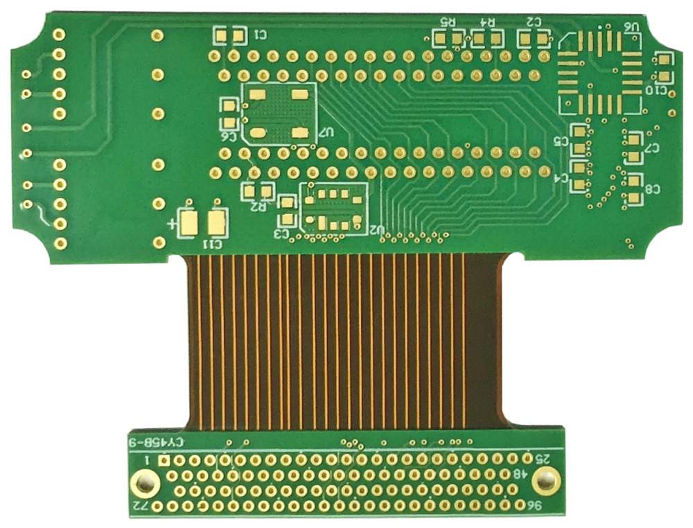
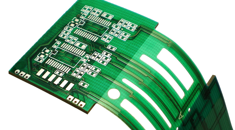
A rigid flex circuit board typically consists of a rigid FR-4 circuit board base laminated with a flexible polyimide layer. The rigid FR-4 material provides structural support and facilitates mounting and connecting electronic components. The flexible polyimide material allows the board to bend and fold around device components and in three-dimensional form factors.
Rigid flex circuits integrate the best properties of both rigid PCBs and flexible PCBs into a single circuit board:
- Rigidity – for structural support and component mounting
- Flexibility – for dynamic and three-dimensional designs
- Durability – withstands flexing and bending
- Reliability – proven PCB technology
- Complexity – increased wiring density
- Weight savings – thinner and lighter than rigid-only boards
This powerful combination makes rigid flex circuits ideal for complex and tightly packed electronic devices where flexibility, reliability, and space savings are critical requirements.
Rigid Flex Circuit Board Design
Rigid flex circuit boards can be designed in many configurations to meet the specific needs of the electronic device. Here are some common design elements:
- Rigid sections – provides stiffness and facilitates component mounting. Often placed at connections and high-stress areas.
- Flexible sections – allows dynamic flexing and folding. Polyimide film or Kapton material.
- Hinges – connects the rigid sections and allows controlled bending. Configured to optimize flex life.
- Stiffeners – additional layers to provide strengthened rigid sections for components or connectors.
- Flat ribbon interconnects – extended flexible sections to connect distant sections.
- 3D formed interconnects – molded interconnections for complex 3D configurations.
- Plated holes – provide enhanced reliability for connections between rigid and flex sections.
- Adhesives – bond flex layer to rigid sections. Ensure bond reliability under dynamic conditions.
Proper design is essential for creating a rigid flex circuit board optimized for mechanical stability, flex life, electrical connectivity, and manufacturability. Rigid flex requires specialized design tools and an understanding of the complex interactions between the rigid and flexible materials.
Benefits and Applications of Rigid Flex Boards
Rigid flex PCBs provide unique benefits that make them an ideal solution for many modern compact and flexible electronic products:
Space and Weight Savings
Rigid flex PCBs can condense and simplify complex wiring using dynamic folds, bends, and formed interconnects. This 3D configuration capability allows for tighter packaging, smaller product size, and significant space/weight savings compared to rigid PCBs alone.
Increased Reliability
The flexible sections of rigid flex boards can withstand vibration, shock, and repeated dynamic flexing. They eliminate the need for discreet wires or connectors – providing enhanced mechanical and electrical reliability.
Design Flexibility
Rigid flex allows for very creative and complex PCB designs not feasible with rigid technology. Dynamic folds and 3D formed interconnects enable innovative industrial design features and ergonomics.
Single Board Solution
Consolidating rigid and flex PCBs into one integrated assembly simplifies manufacturing. Rigid flex eliminates the need to interconnect separate rigid and flex boards.
Cost Savings
Despite higher flex material costs, rigid flex PCBs can significantly reduce overall system cost through space savings, simplified assembly, and fewer interconnects.
With these benefits, rigid flex circuit boards are increasingly used in the following applications:
- Aerospace and Defense Electronics
- Industrial Electronics
- Medical Electronics
- Consumer Wearables and IoT Products
- Mobile and Handheld Devices
- Automotive Electronics
- Robotics and UAVs
Any product that demands compact, lightweight, and highly reliable electronics is a potential fit for rigid flex circuit technology. The expanding capabilities of rigid flex are enabling many new innovative and cutting-edge electronic product designs.
Rigid Flex PCB Materials and Construction
Rigid flex boards require specialized materials engineered to deliver the ideal balance of properties demanded in flexing rigid boards.
Rigid Layers
The rigid sections of the PCB typically use FR-4 glass reinforced epoxy. FR-4 provides structural stability for mounting components and connectors while withstanding flexing stresses. High Tg FR-4 grades are often preferred.
Flexible Layers
The flexible layers use polyimide films such as Kapton or UPILEX. These high-reliability polymer films provide excellent flex life, temperature resistance, and electrical insulation. Typical thicknesses range from 13um to 75um. Adhesive flex layers bond the polyimide to adjacent rigid layers.
Bonded Construction
The rigid and flexible layers are bonded together using advanced adhesive systems designed to withstand dynamic bending stresses. Multiple bonding and preparation steps ensure maximum adhesion strength for flexing reliability.
Plated Holes
Plated through holes and other vertical interconnect technologies provide reliable connectivity between the rigid and flex layers under dynamic conditions. Careful hole drilling and plating is critical.
Stiffeners and Shielding
Additional stiffening layers are often used to augment the thickness of rigid sections for enhanced component mounting. Copper layers or aluminum heat sinks can be added. Shielding layers may also be included.
Hinge Design
Hinges connect the rigid sections and manage the bending and flexing. Their design, position, and materials are optimized to achieve the target flex life for the application.
Solder Mask and Finishes
Solder masks, typically LPI, help avoid shorting between traces while enabling soldering. Various surface finishes such as ENIG, Immersion Tin, or HASL suit the soldering method and reliability requirements.
Rigid Flex PCB Fabrication and Assembly
Producing quality rigid flex boards requires advanced fabrication capabilities and processes fine-tuned for flex-rigid construction.
Fabrication Capabilities
- Fine line PCB processing down to 8um line widths and spaces.
- Thin core rigid and flex layer laminations.
- Sequential bonding with multiple adhesive treatments.
- Laser and mechanical micro-via formation.
- High-reliability plated through holes.
- Flex-rigid panelization and breakout.
Critical Processes
- Layer stacking with precision alignment of flexible and rigid layers.
- Curing and preparation of adhesive systems.
- Drilling of small holes for interconnects.
- Surface preparations to ensure bond integrity.
- Fine line etching of thick copper traces.
- Plating of holes and traces.
Testing
- Net integrity testing of traces.
- Ionic cleanliness verification.
- Flexibility and bend cycle testing.
- Environmental stress testing.
- Visual inspection of plating, bonds, and features.
Assembly
Rigid flex PCB assembly requires specialized flex-capable processes. The boards are typically populated in the flat state before dynamic installation. Precise application of adhesives and fastening hardware is critical.
Rigid Flex Design Guidelines
To achieve successful and reliable rigid flex circuits, designers should follow a set of design-for-manufacturing (DFM) guidelines and rules. Some key guidelines include:
- Minimize unsupported spans of flex layers to avoid sagging.
- Include stiffening elements for strengthened mounting regions.
- Use generous bend radius at hinge areas.
- Allow sufficient adhesive bonding area between rigid and flex layers.
- Enable top and bottom layer alignment precision for small features.
- Account for coefficients of thermal expansion between materials.
- Plan panel utilization and breakout to minimize flex handing.
Early collaboration between designers and manufacturers ensures DFM guidelines are met from the initial concept stages. With proper design, rigid flex PCBs deliver the enhanced reliability, miniaturization, consolidation, and functionality demanded in advanced portable, medical, aerospace, and defense applications.
FQA
What are some typical applications for rigid flex circuit boards?
Some of the most common applications are aerospace systems, medical devices, military electronics, consumer wearables, mobile phones, automotive electronics, robotics, and internet of things (IoT) products. Any application needing lightweight, dynamic, and highly reliable interconnect can benefit from rigid flex technology.
What are some key differences between rigid PCBs and flex PCBs?
Rigid PCBs use stiff insulating boards and are better for physically supporting and mounting components. Flex PCBs utilize flexible polyimide films and are ideal for moving or dynamically flexing circuits. Rigid flex combines both into one integrated circuit board solution.
How does the cost compare between rigid flex boards and rigid PCBs?
Despite the higher cost of the flexible material layers, rigid flex PCBs can provide overall system cost savings by consolidating assemblies, eliminating connectors, and enabling space/weight optimizations. However, cost should be evaluated on a case-by-case basis.
What are some considerations for rigid-to-flex layer alignment?
Maintaining precision alignment of the thin flexible layers to the rigid layers is critical for reliable interconnects. Factors like coefficient of thermal expansion mismatch between the materials and specific fabrication steps impact alignment precision during lamination and drilling.
How many bend cycles can a rigid flex board withstand?
Achievable bend cycles depend on several factors like flex layer materials, trace geometries, dynamic bending stresses, and hinge design. Typical rigid flex constructions can accommodate hundreds of thousands to millions of dynamic bend cycles for long service life.