


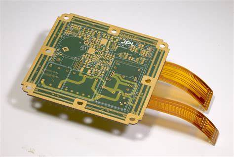
Rigid flex circuits, also known as rigid flexible printed circuit boards (PCBs), are a specialized type of printed circuit board that consist of rigid and flexible substrates laminated together. The rigid sections provide mechanical support while the flexible sections allow dynamic flexing, bending or wrapping around components. Rigid flex circuits are increasingly being used in modern electronic devices to meet demands for miniaturization, high-density interconnections, 3D assembly and improved reliability.
Design Considerations for Rigid Flex Circuits
Designing rigid flex circuits requires careful planning to optimize the placement of components, routing of traces, and integration of the rigid and flex sections. Here are some key design considerations:
Component Layout
Components need to be strategically placed across rigid and flex areas. High profile components are often mounted on the rigid portions while lower profile components can be placed on the flex areas.
Routing Traces
Traces should be routed along the rigid portions as much as possible, limiting the number of traces running through dynamic flexing areas. This helps minimize the risk of traces cracking under repeated bending stress.
Stiffening Elements
Short spans of rigid stiffeners can be added along flex sections to provide mechanical support and prevent unwanted twisting or folding.
Layer Stackup
The rigid sections typically have a thicker dielectric for insulation while the flex sections have a thinner, more flexible dielectric layer. The layer stackup must transition smoothly between the areas.
Bend and Fold Relief
Relief features like rounded corners, tear drops, and curved edges help prevent excessive wear and cracks during flexing. Minimum bend radii need to be maintained.
Strain Relief
Features to provide strain relief should be added where the rigid and flex sections meet to avoid delamination or board damage during movement. Common methods include anchor bars, floating islands or complex geometries.
Testability
Test points, vias and other design elements to improve test access should be considered to enhance manufacturability and improve quality control.
Manufacturing Processes
Rigid flex PCBs require specialized fabrication capabilities to handle the combination of rigid and flexible materials in one circuit board. Here are some of the key manufacturing processes:
Layer Laminations
The rigid and flexible layers are precisely laminated together using adhesive films. The process requires careful alignment and smooth transitions between sections.
Imaging and Etching
After lamination, the conductive copper layers are imaged with solder mask and etched to produce the circuitry pattern. The etching process must accommodate both rigid and flexible substrates.
Hole Drilling
Holes are drilled through the board to facilitate component mounting and interlayer connections. The rigid areas allow smaller diameter holes while flex areas require larger sizes to avoid cracking.
Joining and Assembly
Soldering or adhesives are used to mount components on the board. Strain relief features are incorporated at the rigid-flex junctions. Automated assembly lines manipulate the flexing areas.
Testing
Rigid flex boards go through extensive functional testing. This includes flex cycle testing where the board is repeatedly bent and twisted to validate robustness.
Singulation
Individual PCB sections are cut or routed out from the full circuit panel. Precise tooling and registration is needed to avoid shifting of flexible areas.
Protective Coatings
Conformal coatings, encapsulants or protective sleeves are often applied to shield the flexing regions from the environment and prevent damage during usage.
Applications of Rigid Flex Circuits
The combination of rigid stability and dynamic flexing provided by rigid flex circuits make them ideal for many applications, including:
- Foldable mobile devices – Laptops, phones and tablets with foldable displays integrate rigid flex circuits to connect the screen across hinges or sliding joints.
- Wearable technology – Curved rigid flex boards allow smart watches, fitness bands and VR headsets to wrap around contours comfortably.
- Medical electronics – X-ray detectors, patient monitors and surgical tools use rigid flex to fit onboard complex, compact devices and enable precise positioning.
- Industrial cameras – Pan and tilt circuitry in cameras benefit from rigid sections for stability and flexible parts for adjustable viewing angles.
- Automotive electronics – Headlight adjusters, powered seats and navigation displays in cars are able to move and adjust using rigid flex board integration.
- Robotics – The dynamic movements of robot arms and joints are enabled by rigid flex circuits rather than loose wires and cables.
- Consumer electronics – Game controllers, wireless earbuds and handheld electronics achieve complex mechanical integration with rigid flex.
Here’s a summary comparing some key properties of rigid flex circuits versus conventional PCBs:
| Property | Rigid Flex Circuits | Conventional PCBs |
|---|---|---|
| Dynamic Flexing | Yes | No |
| 3D Assembly | Allows compact 3D stacking | Limited to 2D |
| High Density | Allows flexible component placement | Rigid surface limits density |
| Reliability | Excellent with proper design | Prone to cracked solder joints from vibration/shock |
| Miniaturization | Smaller and thinner overall profile | Rigid board and loose cabling take up more space |
| Customization | Can be uniquely shaped and formed | Limited to rectangular boards |
| Cost | Typically higher | Lower cost from economies of scale |
Frequently Asked Questions
Here are some common questions about rigid flex circuits:
Q: What are the typical materials used in rigid flex circuit construction?
A: The rigid sections of the PCB are usually standard FR-4 material while the flexible sections use polyimide or polyester films. Adhesive layers bond the materials together.
Q: Can components be mounted directly on the flexing portions of the circuit?
A: It is generally advised to mount components only on the rigid sections. But smaller, lighter components can sometimes be safely mounted on dynamic flex areas with proper stress relief.
Q: What are some limitations of rigid flex circuits?
A: Limitations include higher costs compared to rigid PCBs, challenging manufacturability for complex or dense designs, and durability issues if not properly designed for flexing.
Q: How many bend cycles can a rigid flex circuit typically withstand?
A: The flex life depends heavily on the design – trace widths, bend radii, materials used, etc. But generally rigid flex circuits can withstand hundreds to thousands of dynamic bend cycles with proper design.
Q: How are rigid flex PCBs tested?
A: In addition to standard electronic testing, specific tests like dynamic bend cycle testing, torque testing, vibration testing, and environmental chamber testing are used to validate the performance of rigid flex circuits.
In summary, rigid flex PCB technology enables electronics designers to incorporate both stable, rigid sections and dynamic, flexing sections into a single circuit board. With proper design and manufacturing considerations, rigid flex circuits can maximize reliability, miniaturization and motion capabilities compared to conventional PCBs. The demand for rigid flex continues to grow as electronics become more compact and complex across industries ranging from consumer devices to medical equipment.