


Introduction to Rigid Flex Circuits
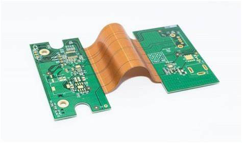
Rigid flex circuits, also known as flex-rigid circuits, are a type of printed circuit board (PCB) that consist of rigid and flexible substrates laminated together. The rigid sections provide mechanical support and mounting points, while the flexible sections allow dynamic flexing and connections between components.
Rigid flex circuits open up new possibilities in product design and miniaturization that cannot be achieved with rigid PCBs alone. They allow three-dimensional construction and dynamic flexing to connect components mounted on surfaces that are offset, hinged, folded, or otherwise moving relative to each other. This enables more compact and lightweight product designs.
With rigid flex circuits, the rigid portions can be designed with very fine traces and spacing for high density interconnections, while the flexing portions can have looser tolerances to accommodate the dynamic movement. Rigid flex combines the best of both rigid and flex circuit technologies in one high performance design.
Applications of Rigid Flex Circuits
Some of the key applications that benefit from rigid flex circuit technology include:
- Laptops, tablets, and mobile devices with hinged displays and bodies
- Foldable smartphones and electronics
- Medical devices like hearing aids, insulin pumps, and wearables
- Industrial cameras with moving lens assemblies
- Automotive camera systems and sensors
- Printers and business machines
- Aerospace and military systems
- Consumer products with folding or motion
Essentially any application where components need to interconnect across surfaces that bend, fold, or move can benefit from the unique advantages of rigid flex circuit construction.
Rigid Flex Circuit Materials
Rigid flex circuits are fabricated from flexible circuit materials laminated with rigid laminate substrates. This allows both properties to be combined into one circuit assembly.
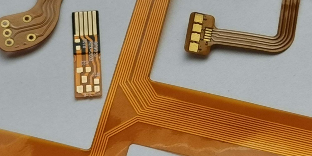
Flexible Substrate Materials
The flexible sections are constructed from thin layers of flexible copper clad laminates that can be bent repeatedly without damage. Typical flexible laminate materials include:
- Polyimide (PI): Kapton is one well known brand of polyimide flexible material. Polyimide has excellent electrical properties and high temperature resistance. It has good chemical resistance and dielectric properties. Polyimide tends to be more expensive but offers the best overall flex capabilities.
- Polyester (PET): Polyester, also known as polyethylene terephthalate (PET), is another common flex circuit substrate. It is not as heat resistant as polyimide but provides good flex durability at a lower cost. Polyester has good chemical resistance.
- PEEK: Polyetheretherketone (PEEK) substrates provide even higher temperature resistance than polyimide, with excellent chemical resistance. PEEK is typically more expensive but suitable for very high temperature or harsh environment applications.
Rigid Substrate Materials
Common rigid materials laminated in rigid flex circuits include:
- FR-4: The most common and affordable rigid PCB substrate is FR-4, which is a fire retardant woven fiberglass core with an epoxy resin binder. FR-4 provides good mechanical support and is suitable for most consumer and industrial electronics.
- Polyimide: Rigid polyimide laminates are also available for very high temperature or flexible applications requiring superior thermal performance.
- Aluminum core: Metal core PCBs with aluminum substrates provide the most rigid support option. Aluminum backed boards offer thermal dissipation while remaining lightweight.
- CEM-1, -3: Woven cotton paper reinforced substrates are lower cost options for less demanding rigid sections.
- Rogers: High frequency boards may use specialized rigid laminates, such as Rogers RO4003C, for excellent electrical performance needed in RF designs.
Rigid Flex Layer Stackup
The cross sectional layer stackup of a rigid flex board will contain both the rigid and flexible materials bonded together. Here are some typical rigid flex layer configurations:
Two Layer Flex-Rigid
A 2 layer rigid flex has a simple construction of a flexible dielectric bonding the rigid sections:
The rigid sections can have fine lines and spaces, while the flex area supports dynamic bending. Components mount on the rigid areas, and traces route through the flex to connect them.
Multilayer Rigid Flex
More complex rigid flex circuits can have 4, 6, 8, or more layers of circuitry. These contain multiple laminated layers of rigid and flex core materials:
High layer count rigid flex allows very dense, complex wiring and stacking of components. The rigid areas provide mechanical support and heat dissipation, while the flex allows dynamic interconnections.
Design Guidelines
Rigid flex circuits require careful design both electrically and mechanically. Here are some key guidelines for reliable performance.
Layer Stackup
- Place ground and power planes adjacent to outer layers for shielding and stability.
- Use thicker copper (2 oz or 3 oz) for power and ground to handle higher currents.
- Include cover layers (soldermask over bare copper) for outer layers when possible.
- Maximize the number of layers in the rigid sections for routing density.
- Use only 2-4 layers in the flexing sections for best dynamic bending.
Board Layout
- Place components only in the rigid sections, not the flexing areas.
- Avoid rigid-to-rigid joints across the flex area for maximum flexibility.
- Provide large bend radius transitions from rigid to flexing areas.
- Route critical signals through the rigid sections first, limiting the traces in the dynamic flex areas.
Component Placement
- Position components on alternating sides of the rigid portions to balance stresses.
- Group high power components together for localized heat dissipation.
- Place large connectors and heat sinks over rigid sections.
- Ensure clearance for any components that need to plug in or attach to the rigid areas.
Flexing Regions
- Design the flexing areas to bend only in the specified directions during use.
- Determine the required bend radius based on the flexible material properties.
- Watch out for pinch points where rigid sections come together, limiting flex.
- Use slits or cutouts to provide stress relief in the flexible areas.
Electrical Considerations
- Use impedance matched controlled routing in the rigid sections for high speed signals.
- Select flex materials to match the target impedance values.
- Use wider traces or reference planes for high current power circuits.
- Allow for capacitance changes in dynamic flexing portions in your design.
- Consider flex and vibration effects on sensitive components.
By following sound rigid flex design practices, you can successfully implement these advanced circuits and take advantage of their unique benefits. Rigid flex opens up new possibilities in electronic product design.
Rigid Flex PCB Manufacturing Process
Producing reliable, high quality rigid flex circuits requires specialized fabrication processes. Here is an overview of how they are manufactured for volume production.
Layer Preparation
The process starts with preparing the separate rigid and flexible core layers:
- Rolls of the flexible substrate material are laminated with copper foil on one or both sides.
- Sheets of the rigid materials are also laminated with copper layers.
- Photoresist is applied to the copper layers on both rigid and flex cores.
Imaging
Next, photolithography is used to image the conductors onto each layer:
- The photoresist is exposed to UV light through artwork masks.
- The unexposed areas are washed away, leaving a pattern of bare copper traces defined.
- Etching removes copper from the unmasked areas, isolating the conductors.
Lamination
The rigid and flexible layers are precisely aligned and laminated together:
- Sheets of adhesive bond the materials under heat and pressure.
- Alignment targets ensure the layers are perfectly stacked.
- Multi-opening presses allow different temperature/pressure profiles.
Drilling
- Small holes are precision drilled through the rigid and flex areas.
- Excellent drill location accuracy and exit quality are essential.
- Burrs are removed and holes cleaned.
Plating
- Copper electroplating makes conductive connections through all layers.
- Plated through holes (PTHs) connect traces across the rigid flex circuit.
- Dense, void-free copper deposits are needed for reliability.
Solder mask
- Soldermask is screen printed or laminated over the outer layers.
- Openings precisely expose underlying component pads and contacts.
Finishing
- Hot air solder leveling (HASL) applies solder coating to exposed pads.
- Immersion silver or gold provides higher performance finish.
- Routed cutouts, slits, scoring lines are made if needed.
- Soldermask coating is applied to edges for protection.
- 100% electrical testing checks continuity, shorts, and function.
Rigid flex manufacturing demands expertise in both rigid and flex PCB processes to deliver high quality, reliable boards. Work with an experienced, capable manufacturer on your next rigid flex project.
Benefits of Using Rigid Flex Circuits
Now that we’ve covered the basics of rigid flex technology and construction, let’s examine some of the key benefits this technology provides:
Enables More Compact, Lower Profile Designs
By folding and bending rigid boards that would otherwise occupy larger planar spaces, rigid flex circuits allow more compact product configurations. Eliminating connectors between separate rigid boards saves space and height.
Provides Flexible Interconnections
The flexible sections enable connections between rigid modules that are moving, offset, or on different planes, which would not be possible with rigid technology alone. Dynamic flexing withstands repeated bends during use.
Combines Rigid and Flex Capabilities
Rigid sections provide mechanical structure for component mounting and containment, while exploiting the fine line capabilities. Flex sections facilitate three-dimensional construction and dynamic movement.
Improves Reliability
Folding rigid boards can eliminate many connectors between PCBs. The reliability of one continuous circuit is higher compared to using discrete flex connectors between individual rigid boards.
Allows Thinner, Lighter Constructions
By replacing thick, heavy rigid boards with thin flexing interconnects, overall weight is decreased. Eliminating discrete connectors also reduces mass.
Simplifies Assembly Processes
With rigid flex, adding connectors during assembly may not be required. Aligning standoff boards, tightening screws, and potential rework is avoided. Automated assembly is easier.
Reduces System Cost
Fewer boards, components, connectors, and manual production steps lower overall costs compared to assemblies using multiple discrete PCBs.
For designs requiring dynamic flexing or compact configurations, rigid flex circuits enable breakthroughs not possible with rigid PCBs alone. Consult closely with your PCB manufacturer to leverage these benefits in your next product.
Frequently Asked Questions
Here are some common questions about rigid flex circuit design and manufacturing:
What are some typical rigid flex applications?
Rigid flex circuits are ideal for products that need to fold, bend, or flex during use, such as laptops, medical devices, industrial cameras, and mobile consumer electronics. Any application requiring interconnections between multiple surfaces or boards can benefit from rigid flex technology.
How many flex/bend cycles can they withstand?
Properly designed rigid flex circuits can endure hundreds of thousands of dynamic flexing cycles during the product lifetime, with flexible layers made using robust polyimide or polyester materials. Careful flex zone design and bend radius control help achieve maximum cycle life.
What are the limitations of rigid flex PCBs?
There are some limitations to consider. The circuits can be more complex to design properly compared to simple rigid boards. Layer count in the flex areas is limited to 2-4 layers typically due to flexure stresses. The flexible dielectric materials can have higher losses at high frequencies compared to rigid boards.
How thick can rigid layers be?
Rigid layer thicknesses from 0.4mm to over 3mm are possible, with 1.6mm being typical for a mid-range 6-8 layer count board. Aluminum or thicker cores provide the most rigid support for high layer counts, large components, and thermal demands.
What are considerations for selecting flex vs. rigid sections?
Determine what areas require static structural support or component mounting versus flexible interconnections. High density routing and power distribution favor rigid sections. Dynamic folding regions are ideal for the flex sections. Analyze the required bending motion and forces.
Summary
Rigid flex PCB technology opens up new possibilities in electronic product design, enabling compact, lightweight constructions and flexible interconnections between modules. By combining the capabilities of rigid and flexible circuits, rigid flex allows configurations not realizable with rigid PCBs alone. With sound design practices and a quality PCB manufacturer, engineers can take full advantage of the benefits of rigid flex construction. This powerful technology enables the demanding and complex designs at the heart of modern electronic devices.