

Introduction to Flex Rigid PCBs
Printed circuit boards (PCBs) provide the foundation for almost every electronic device we use today. From computers and smartphones to kitchen appliances and vehicles, PCBs allow various electronic components like chips and capacitors to be interconnected and communicate.
As electronic devices become smaller and more portable, there is a growing need for PCBs that are compact and can flex and bend. This is where flex rigid PCBs come into play.
What are Flex Rigid PCBs?
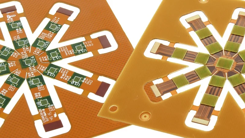
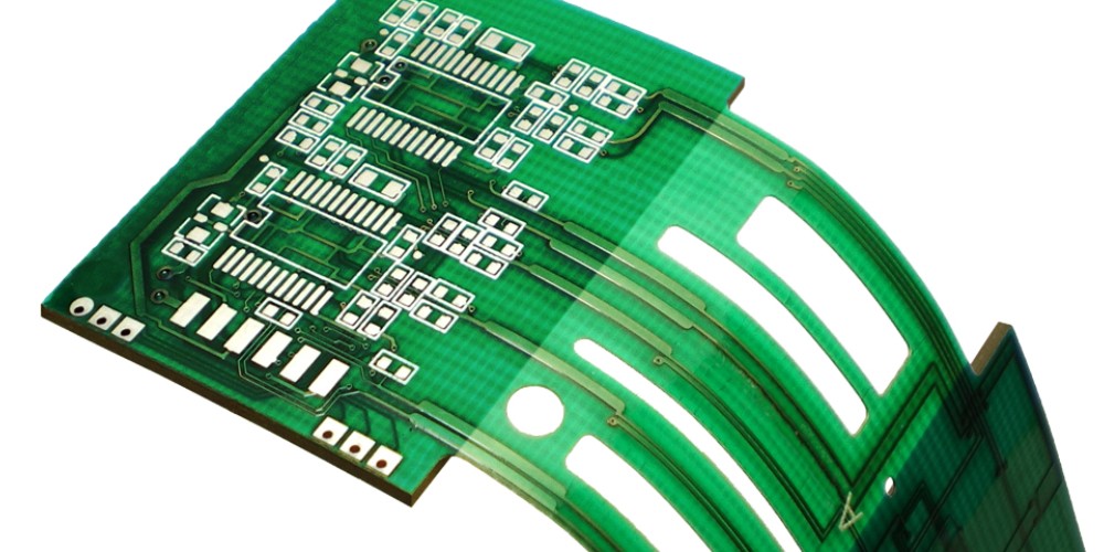
A flex rigid PCB is a special type of printed circuit board that consists of both rigid and flexible substrate materials. Simply put, rigid sections provide sturdiness while flexible sections allow the PCB to bend and flex.
Flex rigid PCBs provide the best of both worlds – the support and stability of a rigid PCB combined with the flexibility to shape around devices and move dynamically. They allow for complex circuity designs in compact spaces and three-dimensional layouts.
Benefits of Flex Rigid PCBs
There are several key benefits that make flex rigid PCBs advantageous for many modern electronic devices:
Compact Size
By incorporating flexible folds and bends, flex rigid PCBs can fit into tight spaces and integrate seamlessly into devices. This allows for smaller and more lightweight product designs.
Dynamic Movement
The flexing regions of the PCB allow it to make dynamic movements, rotations, and adjustments as needed. This is especially useful in devices like laptops and mobile phones.
Reliability
Rigid-flex PCBs are extremely durable and resistant to vibrations and mechanical stress. The rigid areas prevent failures while the flex areas can repeatedly bend without wear and tear.
Design Freedom
With both rigid and flexible substrates, designers have more freedom to place components and route traces in 3D space. This enables more compact and optimized PCB layouts.
Cost Savings
By consolidating rigid and flex PCBs into one assembly, flex rigid PCBs can significantly reduce manufacturing costs. The combined approach reduces the number of connectors needed.
Construction of Flex Rigid PCBs
The construction of flex rigid PCBs involves combining rigid boards and flexible circuits into one cohesive unit using special manufacturing techniques. Here are some key points on how they are fabricated:
- Rigid layers – Rigid PCB layers are made from typical rigid substrate materials like FR-4. Multiple layers can be stacked using interlayer bonding.
- Flexible layers – Flexible layers are made from polyimide films like Kapton. Thin copper traces are laminated on the polyimide.
- Bonding – Adhesive materials are used to bond the rigid and flex layers together firmly. Acrylic or polyimide adhesives are commonly used.
- Covers and Stiffeners – Covers such as solder masks and stiffeners like aluminum bars can be added to protect flexible areas.
- Vias and Buried Vias – Small plated through holes connect traces between layers in rigid areas, while buried vias connect traces in flexible areas.
- Bend Areas – Flexing regions have fewer copper traces, allowing the PCB to bend and fold repeatedly.
Types of Flex Rigid PCBs
There are several configurations and classifications of flex rigid PCBs based on the layout of the rigid and flexible substrates:
Single Sided Flexible
- One rigid PCB layer
- One layer of flexible substrate
- Traces and components only on rigid side
- Lowest cost configuration
Double Sided Flexible
- One rigid PCB layer
- Flex layers on both sides
- Allows traces and components on both sides
Multilayer Flex Rigid
- Multiple alternating rigid and flex layers
- Flex layers folded in “z” shape
- Complex layout with traces routed across various rigid and flex layers
- Used in advanced, compact designs
Rigid Flex
- Multiple smaller rigid boards connected by flex layers
- Rigid islands enable complex component layout
- Allows movement between rigid sections
Flex Rigid Flex
- Flexible sections on both ends of a central rigid section
- Enables unique 3D configurations and motion
Table summarizing the types:
| Type | Description |
|---|---|
| Single Sided Flexible | 1 rigid layer, 1 flex layer on one side |
| Double Sided Flexible | 1 rigid layer, flex layers on both sides |
| Multilayer Flex Rigid | Multiple alternating rigid and flex layers |
| Rigid Flex | Multiple rigid boards interconnected by flex layers |
| Flex Rigid Flex | Flexible sections on both ends of a central rigid section |
Applications of Flex Rigid PCBs
Due to their unique combination of stability, flexibility, and reliability, flex rigid PCBs are utilized in a wide range of modern electronic devices:
- Laptops – The foldable and dynamic nature of flex rigid PCBs make them ideal for integrating keyboards, displays, and other components in laptops while allowing motion and flexibility.
- Mobile Phones – Smartphones take advantage of flex rigid PCBs to connect components like processors, cameras, and displays into very compact spaces and allow the phone to bend and twist.
- Medical Devices – The ability to fit rigid and flex circuits into small spaces is beneficial for endoscopes, hearing aids and other medical devices that need to flex and maneuver through the human body.
- IoT Devices – Flexible segments in rigid boards accommodate the mechanics needed for folding joints in smart watches, fitness bands and other wearable technologies.
- Automotive – Cars are using rigid-flex PCBs for engine control units, in-car entertainment systems, lighting, and other applications requiring vibration resistance and mobility.
- Consumer Electronics – eReaders, digital cameras, and even advanced electric toothbrushes rely on flex rigid PCBs to achieve robust and compact system designs.
In summary, flex rigid PCBs enable the sophisticated and robust, yet compact product designs that are essential across consumer and industrial electronics today. Their unique combination of capabilities are a key enabling technology for modern devices and the Internet of Things.
Design Considerations for Flex Rigid PCBs
Designing a flex rigid PCB requires paying careful attention to the interaction between the rigid and flexible areas throughout the design process:
Layer Stackup
- Plan where each rigid layer and flexible layer is needed. Minimize transitions between rigid and flex.
- Determine optimal substrate materials – typical stackup uses polyimide flex layers and FR-4 for rigid.
Bend Areas
- Minimize traces across bend areas. Use wide bends with maximum radius.
- Use split planes or neck-downs to route traces through bends. Avoid 90 degree bends.
Transitions
- Carefully design borders between rigid and flex areas to avoid stresses.
- Smooth transitions prevent mechanical failures. Reinforce with soldermask/stiffeners if needed.
Components
- Position components in rigid sections of the PCB, avoiding flex areas. This prevents cracked joints.
- Prefer small SMD components. Avoid tall, heavy through-hole parts.
Routing
- Route critical signals through only rigid layers. Use flex layers for low speed traces.
- Watch trace lengths on outer flex layers as dimensions change during bending.
Thermal Management
- Ensure proper thermal design. Heat can impact material performance.
- Allow for heat dissipation in rigid sections. Avoid heat concentration near flex areas.
Testing
- Test via shake, vibration, and repeated bending. Assess impacts across operating temperature range.
- Determine safe bend radius limits and account for in enclosure design.
Trends and Future Outlook
Several trends point toward expanded applications for flex rigid PCBs in the future:
- Miniaturization – As consumer electronics and mobile devices continue to shrink in size, compact and dynamic flex rigid PCBs become more advantageous.
- HDI – The higher densities and finer features of high-density interconnect (HDI) PCB fabrication allow more capabilities to be packed into flex rigid designs.
- 5G – The 5G rollout is enabling high speed, high frequency products that can benefit from the optimized signal and thermal performance of rigid-flex circuits.
- Autonomous Vehicles – Self driving cars and drones are packed with sensors and M2M communication modules that utilize flex rigid PCBs extensively.
- Flexible Displays – Flexible OLED and e-paper displays are an emerging application for flex PCBs as product designers target bendable smartphones and devices.
- Wearables – More advanced health monitors and body-worn devices make ample use of flex rigid PCBs to survive daily bend stress and motion.
In summary, flex rigid PCBs are reaching higher levels of complexity and density, while also finding uses in more applications that require compact electronics able to move dynamically and survive rugged conditions.
Frequently Asked Questions
What are some typical materials used in flex rigid PCBs?
The rigid portions of flex rigid PCBs typically use standard FR-4 substrate, while the flexible sections use polyimide films like Kapton or Apical. Bonding layers usually involve acrylic or polyimide adhesives.
How are components mounted on flex rigid PCBs?
Most components mount on the rigid portions of the PCB using standard SMT assembly. Critical ICs can be affixed to both rigid and flex areas using conductive epoxy glue if required for layout purposes.
How are flex rigid PCBs tested and inspected?
In addition to standard PCB testing like AOI, these boards require specialized inspection of bend areas and validation through repetitive bending, twisting, vibration, and environmental stress tests to ensure robustness.
Can flex rigid PCBs be easily repaired and reworked?
Re-work and repair is very challenging for complex flex rigid PCBs. It often requires complete replacement due to the specialized materials and construction methods. Simpler designs may allow minor repair.
What are some limitations or disadvantages of flex rigid PCBs?
Overall cost can be higher than traditional rigid PCBs. More complex assembly/soldering is required, and the boards can be difficult to inspect or repair after manufacture. Thermal management also requires special attention.
Conclusion
Flex rigid PCB technology offers unique benefits like compact design, dynamic flexing, and rugged reliability, enabling innovation across consumer and industrial electronics. As electronic devices continue getting smarter and more interconnected, flex rigid PCBs provide the perfect combination of compact packaging and robust performance that new products demand. With new opportunities emerging from wearables to IoT systems and autonomous vehicles, this technology will only grow in adoption and become more sophisticated in its implementations. While designers must pay close attention to the specialized construction methods and materials involved, the future looks bright for flex rigid PCBs powering the electronics of tomorrow.