


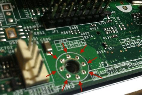
What are Mounting holes?
Mounting holes are holes drilled or punched near the edges of a printed circuit board (PCB) that allow the board to be securely attached or mounted to an enclosure, chassis, or another structure using screws, standoffs, or other fasteners. Mounting holes are essential for ensuring the PCB remains in place and protected from vibration, impact, and other mechanical stresses during use.
Mounting holes come in various sizes and types depending on the specific mounting requirements and the size and weight of the PCB. Some common mounting hole sizes and types include:
| Hole Diameter | Typical Screw Size | Hole Type |
|---|---|---|
| 2.2 mm | M2 | Non-plated |
| 2.7 mm | M2.5 | Non-plated |
| 3.2 mm | M3 | Non-plated or plated |
| 4.2 mm | M4 | Non-plated or plated |
Non-plated mounting holes have no metal plating and provide electrical insulation between the screw and the PCB. Plated holes have a metal coating that electrically connects the screw to the PCB ground plane for shielding.
Other Types of Board Edge Holes
In addition to mounting holes, there are several other types of holes that may be placed near the edges of a PCB for various purposes:
Tooling Holes
Tooling holes are non-plated holes used for aligning and securing the PCB during fabrication, assembly, and testing. They ensure proper registration between the PCB and the manufacturing equipment, such as screen printers, pick-and-place machines, and test fixtures. Tooling holes are typically smaller than mounting holes, with common sizes ranging from 1.5 mm to 3.0 mm in diameter.
Alignment Holes
Alignment holes, also known as locating holes or mating holes, help align the PCB with mating connectors, buttons, LEDs, or other components in the final assembly. These holes are often non-plated and may have tight tolerances to ensure precise positioning. The size and location of alignment holes depend on the specific components being aligned.
Plated Edge Slots
Plated edge slots are elongated openings at the edge of a PCB that allow it to be inserted into a mating connector or card-edge socket. The slots have metal plating on the inside surfaces to form conductive traces that mate with connector contacts. Plated edge slots are commonly found on expansion cards, memory modules, and other plug-in PCBs.
V-Scores
V-scores are shallow grooves cut partway through the PCB substrate along desired break lines to allow the board to be easily separated into smaller sections after fabrication. V-scores are often used for creating snap-apart PCB panels or for separating tab-routed boards. The depth and angle of the V-score depend on the substrate thickness and the desired break force.

Designing Mounting Holes
When designing mounting holes for a PCB, there are several factors to consider:
Hole Size and Placement
Choose appropriate hole sizes based on the type and size of fasteners being used. Holes should be slightly larger than the fastener diameter to allow for easy insertion and alignment tolerances. Holes should also be placed far enough from the board edge and other components to prevent mechanical stress and damage.
Typical minimum distances from the center of a mounting hole to the nearest board edge or component are:
| Hole Diameter | Minimum Edge Distance | Minimum Component Distance |
|---|---|---|
| 2.2 mm | 3 mm | 2 mm |
| 2.7 mm | 3.5 mm | 2.5 mm |
| 3.2 mm | 4 mm | 3 mm |
| 4.2 mm | 5 mm | 4 mm |
Copper Keepout
To prevent electrical shorts and mechanical stress, there should be no copper traces or planes in the area immediately around each mounting hole location. This copper keepout region should extend at least 1 mm beyond the edge of the hole.
Solder Mask and Silkscreen
Solder mask and silkscreen layers should also be kept away from mounting hole locations to prevent contamination and allow for proper seating of fasteners. A minimum solder mask pullback of 0.5 mm and a minimum silkscreen pullback of 1 mm around mounting holes are recommended.
Mechanical Drawings
Include detailed mechanical drawings or hole templates in your PCB fabrication data to clearly communicate mounting hole sizes, locations, and tolerances to your manufacturer. Drawings should specify hole diameters, distances from edges and other features, and any special requirements such as plating or chamfering.

FAQ
How many mounting holes do I need for my PCB?
The number of mounting holes depends on the size and weight of your PCB, the expected mechanical stresses, and the available space for mounting. In general, smaller PCBs up to 50 mm in size can use two mounting holes, while larger or heavier boards may require three or four holes for stable mounting.
Can I use plated holes for mounting?
Yes, plated mounting holes can be used if electrical grounding or shielding of the fastener is desired. However, non-plated holes are more common for simple mechanical mounting, as they provide insulation and prevent shorts. If using plated holes, ensure proper keepout distances from traces and components.
What if my PCB doesn’t have room for dedicated mounting holes?
If space is limited, you can consider alternative mounting methods such as adhesives, tapes, or snap-fit standoffs that attach to the edges or corners of the PCB. You can also use existing holes for components such as connectors or large terminals for mounting purposes, as long as they are properly sized and located.
How do I specify hole tolerances?
Hole tolerances should be specified on mechanical drawings using standard GD&T (geometric dimensioning and tolerancing) symbols and callouts. For example, a 3.2 mm diameter mounting hole with a tolerance of ±0.1 mm would be specified as “Ø3.2±0.1”. Tighter tolerances may be needed for alignment or plated holes, while looser tolerances are acceptable for non-critical mounting.
Can I use different mounting hole sizes on the same PCB?
Yes, you can use different hole sizes for different mounting points or components on the same PCB. Just make sure to clearly specify the sizes and locations of each unique hole type in your mechanical drawings and fabrication data to avoid confusion. Using consistent sizes and patterns when possible can simplify design and assembly.

Conclusion
Mounting holes and other board edge holes are critical features for the mechanical integration and reliability of PCBs. By understanding the different hole types, sizes, and design considerations, you can create PCBs that are easy to assemble, align, and secure in your final product.
When designing mounting holes, remember to:
- Choose appropriate hole sizes and locations based on fasteners and components
- Maintain proper copper, solder mask, and silkscreen keepout distances
- Clearly communicate hole specifications and tolerances in mechanical drawings
- Consider alternative mounting methods if dedicated holes are not feasible
By following these guidelines and working closely with your PCB fabricator, you can ensure your boards have the right mounting holes for your application needs.