


Introduction to Flexible Printed Circuit Boards
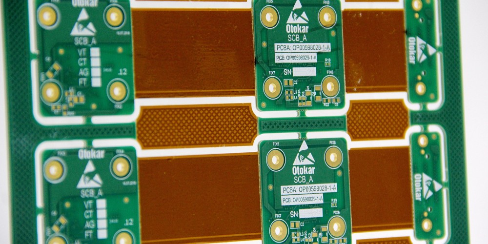
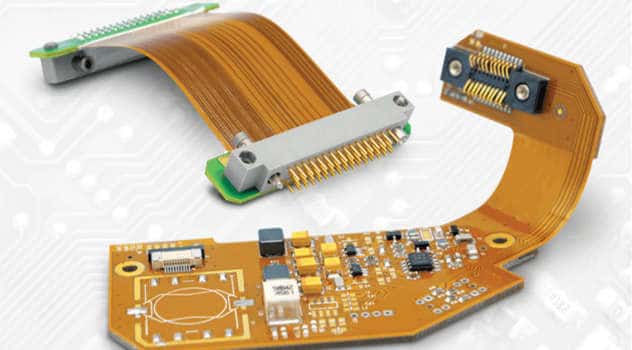
A flexible printed circuit board (flex PCB or flex circuit) is a type of printed circuit board made of a flexible insulating substrate material such as polyimide or polyester. The conductive pathways or tracks are printed or laminated onto the flexible substrate using copper foil.
Flexible PCBs can be bent, folded or twisted to fit into tight spaces and adapt to movement or vibration in electronic devices. They are extremely lightweight and ideal for applications where weight, space, flexibility, or reliability are important factors.
Benefits of Flexible PCBs
- Extremely lightweight and thin
- Can be bent, folded, twisted or rolled to fit small spaces
- Withstand repeated bending cycles and vibration
- Enable flexible or dynamic components and connections
- Facilitate complex and dense interconnections
- Low insertion force for connectors
- Highly customizable shapes and layouts
- Reduce assembly and installation costs
Applications of Flex Circuits
Some common applications of flexible PCBs include:
- Consumer electronics – Cell phones, cameras, display screens
- Medical devices – Hearing aids, blood pressure monitors
- Industrial electronics – Printers, robotics, automation equipment
- Aerospace and military – Avionics, control systems, sensors
- Automotive – Navigation systems, under-the-hood electronics
Flexible PCB Materials and Construction
There are several key materials and components involved in the makeup of a flex circuit board:
Flexible Substrate Materials
The flexible substrate or base material gives the PCB its flexibility and provides electrical insulation between conductors. Common materials include:
- Polyimide (Kapton): Most widely used. Withstands very high temperatures. Good chemical resistance.
- Polyester (PET): Lower cost but has lower temperature tolerance.
- PEN: High temperature performance similar to polyimide.
- Polyurethane: Soft and pliable but lower temperature range.
- Parylene: Used as a moisture barrier coating over other substrates.
Conductors
The conductors provide the electrical connections in a flex circuit.
- Copper traces: Usually electrodeposited or laminated copper foil, ranging from 1 to 3 oz thickness.
- Printed silver inks: Conductive silver inks printed on the substrate. Lower conductivity than copper.
Coverlayers and Coatings
Cover layers help protect the copper from wear and environmental damage. Common options:
- Coverlay: Polyimide laminate layer over conductors.
- Solder mask: Epoxy based coating to prevent solder flow between pads.
- Conformal coating: Thin insulating coating over entire assembly.
Bonded Layers
Multiple layers of substrate with conductive traces can be bonded together using adhesive or thermocompression processes. Multilayer flex circuits support higher complexity and interconnection density.
Stiffeners and Carriers
Optional stiffener materials like polyimide or steel can be added for sections that require rigidity or connectors. Carrier frames support the PCB during manufacturing.
Flexible PCB Design Considerations
Designing a successful flex PCB requires paying special attention to:
- Bend radius: Avoid sharp folds that could damage traces – limit to at least 2x substrate thickness.
- Conductor width and spacing: Thicker copper and wider spacing help improve flexibility.
- Strain relief: Use flexible joints and mechanical compliance to avoid conductor damage.
- Layer stackup: Minimize stressed layers on the outside of bends.
- Adhesives: Choose flexible, low-modulus acrylic or epoxy adhesives.
- Vias: Use filled ink vias instead of plated through holes for reliability.
- Connections: Use flexible interconnects like elastomeric connectors.
- Harnessing: Properly constrain flexing sections while allowing movement.
Careful design prevents trace cracking and connection failure while maximizing flex life.
Flex PCB Fabrication Process Overview
Producing a flexible printed circuit board involves specialized fabrication processes and equipment. Here is a simplified overview of the key steps:
1. Design and Layout
- Create circuit schematic, board layout, and assembly files with CAD software.
- Verify design rules and constraints for flex fabrication.
- Output Gerber files for all required layers.
2. Substrate Preparation
- Select flexible base material (polyimide, polyester, etc).
- Clean substrate and apply adhesion promotion treatment.
3. Copper Foil Patterning
- Laminate copper foil onto substrate using heat and pressure.
- Coat with photoresist and expose using lithography process.
- Etch away unwanted copper to create conductor traces.
4. Core Layer Bonding
- Align and laminate together substrates with traces using adhesive.
- Drill and plate holes to form interlayer connections.
5. Surface Finish
- Apply solder mask over traces for soldering or coatings for protection.
- Print legend for component markings.
6. Final Shaping and Assembly
- Rout outer edges to board outline.
- Install connectors, components and shielding.
- Perform any secondary bending and forming.
Flexible PCB Design Tips
Here are some helpful design practices when laying out flex PCBs:
Trace Width and Spacing
- Use wider traces (5-10 mil) for better flexibility and current capacity
- Increase spacing between traces for critical signals
- Ensure adequate isolation spacing from board edge (20-50 mil)
Bend Areas
- Avoid acute angles – use large bend radii >= 2X substrate thickness
- Stagger traces entering/exiting bend areas
- Place all metal layers on neutral plane in bend areas
Terminations
- Avoid rigid components in flexing sections
- Use flexible ribbon cable or spring contacts for dynamic interconnections
- Anchor flexible sections near terminations to reduce strain
Reinforcements
- Add stiffener material under connectors and components
- Use strategically placed adhesive to control bend areas
- Allow for thermal expansion differences between materials
Vias
- Filled ink vias are preferred over plated holes for dynamic flexure
- Use elongated “mouse bites” to relieve stress around plated holes
Shielding and Ground
- Use flex material with adhesive copper backing for integrated ground plane
- Carefully manage ground returns current through dynamic sections
Table Comparing Flexible Circuit Materials
| Material | Type | Dielectric Constant | Loss Tangent | Temperature Range | Key Properties |
|---|---|---|---|---|---|
| Polyimide | Thermoset polymer | 3.4-3.6 | 0.002-0.01 | -269 to 400°C | Excellent thermal stability and chemical resistance |
| Polyester (PET) | Thermoplastic polymer | 3.2-3.3 | 0.02-0.05 | 130-155°C | Lower cost, easily die cut |
| LCP (Liquid Crystal Polymer) | Thermoplastic | 3-3.2 | 0.003-0.009 | 240-280°C | Extremely low loss, highly stable |
| PEN (Polyethylene Naphthalate) | Thermoplastic | 3.0-3.2 | 0.012-0.018 | Up to 200°C | High temperature performance like polyimide |
| PI/glass | Polyimide reinforced with woven glass fabric | 3.9-4.9 | 0.009-0.02 | -269 to 400°C | Very dimensionally stable, low Z-axis expansion |
| Polyurethane | Thermoplastic elastomer | ~3 | 0.05-0.1 | -40 to 85°C | Flexible and elastic, abrasion/chemical resistant |
| Parylene | Polymeric coating | 2.8 | 0.0002 | -200 to 150°C | Excellent moisture and dielectric barrier |
Benefits of Working with a Flex PCB Manufacturer
While it’s possible to produce simple flex circuits in-house, most projects benefit from partnering with a professional flex PCB manufacturer. Here are some of the key advantages:
- Experience: Flex manufacturers have the expertise and process know-how to properly fabricate circuits and overcome design challenges. They can ensure the flex board is producible and functions reliably.
- Tooling: Flex PCB production requires an array of specialized equipment including etchers, lamination presses, laser direct imaging (LDI), and pick-and-place. Leveraging the manufacturer’s capital investment in these machines is far more cost-effective.
- Volume Production: Contract manufacturers have the facilities and throughput to produce flex PCBs in higher volumes more efficiently once the design is finalized.
- Testing and Inspection: Manufacturers can perform electrical testing, automated optical inspection (AOI), and other quality checks to validate the assembly before shipping.
- Materials and Components: Manufacturers have established supply chains to source all the required flex circuit materials, adhesives, coverlays, connectors, and components.
- Technology: Manufacturers stay current on the latest flex PCB advancements in materials, fabrication processes, design tools and equipment.
Working closely with an experienced flex PCB producer helps ensure efficient design, optimized performance, quality construction, and on-time delivery.
Five Key Questions to Ask Your Flex PCB Manufacturer
When selecting a contract manufacturer for your flex PCB project, here are five important questions to ask:
1. What types of flex materials and constructions do you specialize in?
You want to make sure the manufacturer has expertise in working with the specific base materials and layer configurations needed for your design.
2. What design support do you offer?
Look for advisory services on design-for-manufacturing (DFM) and a review of your flex CAD files to catch any potential fabrication issues early.
3. What range of advanced flex-PCB capabilities do you have in-house?
Seek manufacturers with specialized equipment for processes like laser direct imaging (LDI), accurate registration between layers, controlled impedance traces, microvias, etc.
4. How much experience do you have serving my target application industry?
Leading manufacturers will have proven experience fabricating flex boards for your specific application area and can share relevant examples.
5. How will you verify quality and performance?
You want robust inspection, testing and quality control to ensure the flex PCBs function reliably. Ask about capabilities like electrical testing, thermal stress tests, AOI, etc.
Selecting an expert flex PCB partner equipped to deliver on your specific requirements ensures a successful project.
Conclusion:
Flexible printed circuit boards enable lightweight, dynamic, and space-saving electronic assemblies in a diverse range of products. While designing flex PCBs requires special considerations, partnering with an experienced flex circuit manufacturer makes it possible to produce small or large volumes cost-effectively. Working closely with your flex PCB producer to optimize the design and fabrication processes results in high-quality flexible assemblies with maximum reliability and functionality.