


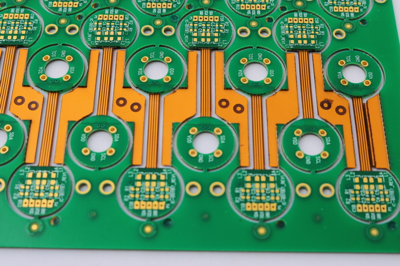
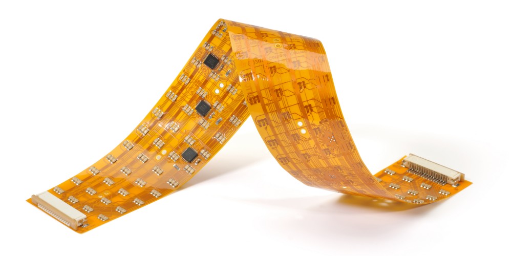
Introduction to Flex Circuits
A flex circuit, also known as a flexible printed circuit board (PCB), is a type of circuitry made from flexible polymer substrates like polyimide or polyester. The circuits can be screened or printed onto the flexible base material to create interconnects between components. Flex circuits allow for dynamic flexing, bending and folding of circuits without damage to circuit integrity. They are commonly found in consumer electronics, medical devices, industrial equipment and aerospace applications.
Flex circuits provide several advantages over traditional rigid PCBs:
- Dynamic flexing capability
- Thin, lightweight and compact
- High reliability
- Advanced design flexibility
- Miniaturization capabilities
Flex circuits are ideally suited for applications where flexibility, space savings, weight reduction or vibration/shock absorption are required. They can wrap around components or enable connections in tight spaces where rigid boards won’t fit.
Flex Circuit Materials
The base substrate, conductors, adhesives and cover layers comprise the materials used in flex circuit fabrication:
- Base substrate – Typically a thin (12.5-250 micron) polyimide or polyester film. Provides mechanical support. Popular films include Kapton, Upilex and Melinex.
- Conductors – Usually copper foil laminated onto substrate. Can be etched to form circuit traces. Other options are conductive inks or films.
- Bonding adhesives – Acrylic or epoxy adhesives bond multiple layers. Popular are Pyralux acrylic adhesives.
- Cover layers – Polyimide films with acrylic adhesive protect and insulate conductors. Common are laminated Kapton films.
- Stiffeners – Optional rigid sections can be added for component areas. FR-4, polyimide or plastic are often used.
- Terminations – Pads/lands allow connections to components via soldering or sockets. May be plated with solder, tin, gold.
Flex Circuit Fabrication Process
Flex circuit manufacturing involves many specialized processes adapted from rigid PCB fabrication. Here are the typical steps:
1. Design and Layout
- Circuit requirements defined
- Schematics created
- Board layout completed
- Mechanical requirements considered
- CAD software creates layout/design files
2. Base Material Lamination
- Adhesive-coated flexible substrate and copper foil are laminated together under heat and pressure
- Single or double-sided material can be produced
- Rolls of raw laminate are typically procured
3. Imaging
- Photoresist applied to copper layers
- Image of circuit layout transferred to layers using phototools
- Exposed areas polymerize on negative acting resist
- Unexposed resist washed away
4. Etching
- Etchant chemicals dissolve copper not protected by photoresist
- Ammoniacal etchants commonly used
- Etching forms circuit traces, pads, vias
5. Resist Strip
- Residual photoresist removed
- Aqueous strippers used
- Prepares boards for next steps
6. Hole Formation
- Tooling holes align layers
- Component holes interconnect layers
- Mechanical punching most common
- Laser ablation also used
7. Layer Bonding
- Multilayer circuits formed by bonding stacked layers
- Adhesive-coated insulation films added
- Heat and pressure activate bonding adhesives
8. Outer Layer Imaging
- Dry film or liquid photoresist applied on outer layers
- Same imaging process as inner layers
- Aligns artwork to previous patterns
9. Plating
- Electrolytic plating builds up copper thickness
- Solder, tin, nickel or gold added
- Increases conductivity, aids soldering
10. Final Etching
- Removes thin starting copper
- Leaves conductors with desired plating intact
- Uses same etching process as initial etching
11. Resist Removal
- Remaining photoresist stripped away
- Aqueous process prior to solder mask
12. Solder Mask Application
- Epoxy-based solder mask coats exposed copper
- Provides insulation and protects circuits
- Applied by screen printing, spray coating, etc.
13. Legend Printing
- Identifying nomenclature and markings printed
- Inkjet or screen printing used
- Added before or after solder mask
14. Final Finishing
- Visual inspection for defects
- Electrical testing verifies functioning
- Individual flex circuits routed from panel
- Completed boards shipped to customer
Flex Circuit Applications
Due to their advantages, flex circuits are found in many advanced applications:
Consumer Electronics
- Mobile phones
- Laptops
- Printed circuit assemblies
- Wearables
- Appliances
Automotive
- Flexible interconnects
- Dynamic flex capability
- Vibration resistance
Medical
- Hearing aids
- Diagnostic instruments
- Patient monitoring
Military/Aerospace
- Guidance systems
- Avionics
- Missiles/rockets
Industrial
- Robotics
- Instrumentation
Flex circuits continue finding new applications as technology evolves.
Flex Circuit Design Considerations
Key considerations when designing flex circuits:
- Dynamic flex requirements – Are static or dynamic bends needed? What radius?
- Circuit layout – Optimize layout for flexibility and reliability. Avoid rigid areas.
- Material selection – Match materials to performance needs. Consider flexibility, weight, thickness, etc.
- Layer stackup – Minimize layers. Balance flexibility with capabilities.
- Termination styles – Choose stable, reliable connections like soldered or crimped terminations.
- Shielding – Incorporate shielding materials or layers if needed.
- Stiffening elements – Strategically incorporate rigid sections to aid assembly and connection.
- Tolerances – Account for potential shrinkage or expansion of flex layers.
Involving a flex circuit specialist early in design is recommended to optimize manufacturability.
Common Flex Circuit Guidelines
- Avoid 90° board bends
- Maintain minimum bend radius
- Stagger layers for gradual fold
- Anchor flexing sections for stability
- Avoid unsupported hanging sections
- Manage thermal expansion differences
Quality Control in Flex Circuit Fabrication
Maintaining quality requires process control and testing during multiple fabrication steps:
- Incoming material inspection – Verify base material quality and properties
- Adhesive curing monitoring – Ensure proper heat and pressure applied
- Etching quality checks – Test etchant strength, measure etch rates
- AOI inspection – Automated optical inspection after imaging, etching, solder mask steps
- Layer registration – Use coupons to confirm alignment at layup
- Adhesion testing – Confirm properly cured adhesives between layers
- Plating thickness measurement – Verify thickness uniformity, adhesion
- Impedance testing – Match controlled impedance networks to design
- Electrical testing – Continuity checks and shorts detection
- Final inspection – Dimensional, visual checks against IPC standards
By focusing on quality throughout the process, flex circuit manufacturers can deliver reliable, high-performing products to customers.
Flex Circuit Assembly
Once fabricated, flex circuits move to assembly where components are loaded onto the boards. Common flex circuit assembly techniques include:
- SMT assembly – Surface mount components attached with solder paste and reflow process.
- Hand soldering – Manual soldering of leaded components. Limited for heat-sensitive flex boards.
- Crimped connections – Crimped terminals provide reliable connections to thicker traces.
- Conductive adhesives – Adhesives filled with silver or other conductive fillers. Cure to form bond.
- Press-fit connectors – No soldering required. Components press into plated through-holes for stable interconnect.
- Sockets – Allow insertion of mating connectors or ICs onto flex boards.
Flex-to-rigid interfaces may be required where flex circuits connect to rigid PCBs or components. Careful reinforcement at connections is needed to avoid flex cracks.
Flex Circuit Cost Drivers
Flex circuit fabrication has higher costs than standard rigid PCBs due to specialized materials and processes. Here are the main factors affecting cost:
- Small batch sizes – Economies of scale difficult with prototype volumes
- Multilayer circuits – Each layer adds materials cost and processing steps
- Flex-rigid combinations – More complex integration and assembly
- Exotic materials – Special bases or adhesives add cost
- Finer features – Tighter spacing and traces increase imaging resolution needs
- Plating requirements – Thick copper and special platings require additional steps
- Certification demands – Meeting military and other specs drives cost
- Quick-turn requirements – Expedited orders reduce efficiency
However, flex circuits provide overall system benefits that offset the initial fabrication costs in many cases.
Future Flex Circuit Trends
Emerging trends shaping the future of flex circuit technology include:
- Growing market demand – More manufacturers recognizing benefits of flex circuits over rigid boards.
- Driving towards finer features – Improved imaging allows conductors with <25 micron spacing.
- Advanced flexible substrates – Newer polymer films offer better thermal/chemical resistance.
- Expanding into new applications – Flexible hybrid electronics (FHE) combining flex circuits and other technologies.
- Automated assembly techniques – Robotic flex circuit assembly with vision alignment.
- Improved modeling and simulation – Computer modeling predicts performance. Reduces physical prototyping.
- Design for manufacturing – Early design collaboration between OEMs and flex suppliers. Design for Excellence (DFX).
- Environmental demands – Requiring halogen-free, green materials. Flex substrates from renewable sources.
As flex PCBs gain traction across industries, innovations in materials, processes and design will continue advancing the technology.
Flex Circuit Fabrication FAQ
Here are some common questions about flex circuit fabrication:
Q: Are flex circuits only made from polyimide?
A: No. While polyimide (Kapton) is the most popular flex circuit substrate, others like polyester (PET) and PEN are also used. The material is chosen based on application requirements.
Q: Can flex circuits use surface mount components?
A: Yes. Flex circuits are very compatible with SMT assembly. Components are attached with solder paste and reflow soldering techniques.
Q: How many layers can you make in a flex circuit?
A: Over a dozen layers are possible, but 4-6 total layers are typical. A large number of layers adds complexity and cost.
Q: What are some key tests done on completed flex circuits?
A: Electrical testing, continuity/shorts checks, insulation resistance, dimensional measurements and visual inspection against IPC standards are common quality tests.
Q: How small can the traces and spaces be on a flex circuit?
A: Advanced flex PCBs can achieve trace/space dimensions below 25 microns (0.001″), but 50-100 microns is more common.
Conclusion
Flex circuits provide a unique set of advantages with their dynamic flexibility and advanced fabrication techniques. As electronics manufacturers face demands for smaller, lighter and more complex circuitry, flex circuits deliver solutions not possible with rigid boards. With skilled engineering and manufacturing expertise, flex circuit fabricators enable cutting-edge products across countless markets and applications.