


Introduction to PCBs
A Printed Circuit Board (PCB) is a fundamental component in modern electronics. It is a flat board made of insulating material, such as fiberglass or plastic, with conductive copper traces etched onto its surface. These traces connect various electronic components, such as resistors, capacitors, and integrated circuits, to form a complete electrical circuit. PCBs have revolutionized the electronics industry by providing a reliable, compact, and cost-effective way to manufacture electronic devices.
In this comprehensive guide, we will walk you through the process of designing and manufacturing your own PCBs. Whether you are a hobbyist, a student, or a professional engineer, this guide will provide you with the knowledge and tools necessary to create high-quality PCBs for your projects.
Understanding the Basics of PCB Design
PCB Layers
PCBs can be categorized based on the number of layers they contain. The most common types are:
| PCB Type | Layers | Description |
|---|---|---|
| Single-sided | 1 | Conductive traces on one side of the board |
| Double-sided | 2 | Conductive traces on both sides of the board |
| Multi-layer | 4+ | Multiple layers of conductive traces separated by insulating material |
PCB Materials
The choice of PCB material depends on the specific requirements of your project, such as the operating temperature, frequency, and environmental conditions. Some common PCB materials include:
- FR-4: A composite material made of fiberglass and epoxy resin, widely used for general-purpose applications.
- Polyimide: A high-temperature material suitable for applications that require resistance to extreme temperatures.
- Teflon: A low-loss material used in high-frequency applications, such as RF and microwave circuits.
PCB Components
A wide variety of electronic components can be mounted on a PCB. Some of the most common components include:
- Resistors: Used to limit current flow and provide voltage division.
- Capacitors: Used for energy storage, filtering, and decoupling.
- Inductors: Used for energy storage and filtering in power supply and RF circuits.
- Integrated Circuits (ICs): Complex electronic components that perform specific functions, such as microcontrollers, amplifiers, and sensors.
- Connectors: Used to interface the PCB with external devices or other PCBs.

PCB Design Software
To design a PCB, you will need to use specialized software that allows you to create schematic diagrams and layout the physical components on the board. Some popular PCB design software options include:
Eagle
Autodesk Eagle is a widely used PCB design software that offers a user-friendly interface and a large library of components. It is available in both free and paid versions, making it accessible to hobbyists and professionals alike.
KiCad
KiCad is a free and open-source PCB design software that provides a complete suite of tools for schematic capture, PCB layout, and 3D visualization. It has a growing community of users and developers, ensuring continuous improvements and support.
Altium Designer
Altium Designer is a high-end PCB design software used by many professional engineers and companies. It offers advanced features, such as multi-board design, signal integrity analysis, and automated manufacturing output generation. However, it comes with a steep learning curve and a higher price tag compared to other options.

PCB Design Workflow
The PCB design process typically follows these steps:
- Schematic Design: Create a schematic diagram that represents the electrical connections between components using the chosen PCB design software.
- Component Placement: Arrange the components on the PCB layout, considering factors such as signal integrity, power distribution, and mechanical constraints.
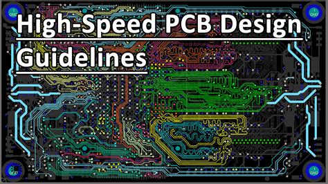
- Routing: Create the conductive traces that connect the components according to the schematic diagram. This step involves defining the trace widths, spacing, and layer assignments.
- Design Rule Check (DRC): Verify that the PCB layout complies with the manufacturing and electrical constraints, such as minimum trace width, clearance, and hole sizes.
- Gerber File Generation: Export the PCB layout as a set of Gerber files, which are the industry-standard format for PCB manufacturing.

PCB Manufacturing Process
Once you have completed the PCB design, you can proceed with the manufacturing process. The main steps involved in PCB manufacturing are:
- Fabrication: The PCB manufacturer creates the bare board using the provided Gerber files. This process involves etching the copper traces, drilling holes, and applying a protective solder mask and silkscreen.
- Assembly: The electronic components are soldered onto the PCB, either manually or using automated assembly machines. This step requires a bill of materials (BOM) and assembly instructions.
- Testing: The assembled PCB is tested to ensure proper functionality and adherence to the design specifications. This may involve visual inspection, electrical testing, and functional testing.
PCB Assembly Techniques
There are two main techniques for assembling components onto a PCB:
Through-Hole Assembly (THA)
Through-hole components have long leads that are inserted into holes drilled in the PCB and soldered on the opposite side. This technique is more suitable for larger components and provides a stronger mechanical connection. However, it requires more manual labor and is less suitable for high-density designs.
Surface Mount Assembly (SMA)
Surface mount components have small leads or pads that are soldered directly onto the surface of the PCB. This technique allows for smaller components and higher-density designs. SMT assembly is more suitable for automated assembly processes, resulting in faster and more consistent production.
PCB Testing and Debugging
After assembling the PCB, it is essential to test and debug the board to ensure proper functionality. Some common testing methods include:
- Visual Inspection: Check for any visible defects, such as solder bridges, missing components, or damaged traces.
- Continuity Testing: Verify that the electrical connections between components are intact using a multimeter or a dedicated continuity tester.
- Power-On Testing: Apply power to the PCB and check for any short circuits, overheating, or unexpected behavior.
- Functional Testing: Test the PCB’s functionality by providing input signals and monitoring the output responses.
If any issues are found during testing, you may need to debug the PCB. This process involves isolating the problem, identifying the root cause, and implementing a solution. Some common debugging techniques include:
- Checking the schematic and PCB layout for design errors.
- Measuring voltages and currents at various points on the PCB using a multimeter or oscilloscope.
- Replacing suspected faulty components.
- Modifying the PCB by cutting traces or adding jumper wires.
PCB Design Tips and Best Practices
To ensure a successful PCB design and manufacturing process, consider the following tips and best practices:
- Start with a clear specification: Define the requirements and constraints of your project before starting the design process.
- Use a modular approach: Divide complex designs into smaller, reusable modules to simplify the design process and facilitate debugging.
- Follow the manufacturer’s design guidelines: Adhere to the PCB manufacturer’s design rules and constraints to ensure manufacturability and reliability.
- Use appropriate component packages: Select component packages that are compatible with your PCB assembly technique and design requirements.
- Consider signal integrity: Minimize noise and crosstalk by using appropriate trace widths, spacing, and termination techniques.
- Plan for power distribution: Ensure that your PCB has adequate power and ground planes to distribute power evenly and minimize voltage drops.
- Incorporate test points: Include test points on your PCB to facilitate testing and debugging.
- Document your design: Maintain clear and comprehensive documentation, including schematics, PCB layouts, BOMs, and assembly instructions.
Frequently Asked Questions (FAQ)
- What is the difference between a schematic and a PCB layout?
A schematic is a symbolic representation of the electrical connections between components, while a PCB layout is the physical arrangement of components and traces on the board. - Can I design a PCB without using specialized software?
While it is theoretically possible to design a PCB manually, using specialized PCB design software is strongly recommended to ensure accuracy, efficiency, and adherence to design rules. - How much does it cost to manufacture a PCB?
The cost of PCB manufacturing depends on factors such as the board size, layer count, quantity, and turnaround time. Prices can range from a few dollars for small, simple boards to hundreds of dollars for large, complex designs. - What is the minimum trace width and spacing for a PCB?
The minimum trace width and spacing depend on the PCB manufacturer’s capabilities and the specific design requirements. Typical values range from 0.1mm to 0.2mm for trace width and spacing. - How long does it take to manufacture a PCB?
The manufacturing time for a PCB depends on the complexity of the design, the chosen manufacturer, and the selected turnaround time. Standard lead times range from a few days to several weeks, while expedited services can provide faster turnaround times at a higher cost.
Conclusion
Designing and manufacturing your own PCBs can be a rewarding and educational experience. By understanding the basics of PCB design, using appropriate software tools, and following best practices, you can create high-quality PCBs for your projects. This comprehensive guide has provided you with the knowledge and resources necessary to embark on your PCB design journey.
Remember to start with a clear specification, use a modular approach, and adhere to the manufacturer’s design guidelines. Test and debug your PCBs thoroughly to ensure proper functionality and reliability. With practice and persistence, you will be able to create increasingly complex and sophisticated PCBs that meet your project requirements.
As you continue to explore the world of PCB design and manufacturing, keep learning and staying up-to-date with the latest technologies and techniques. The electronics industry is constantly evolving, and there is always more to discover and create. Happy PCB designing!