


Flexible printed circuit boards (FPCBs) are a type of printed circuit board made using flexible substrate materials like polyimide or polyester. Unlike traditional rigid PCBs, flex circuits can bend, fold and flex to accommodate different form factors and mobile or dynamic applications. FPCBs allow circuitry to move freely while still maintaining electronic connections. They are ideal for products where flexibility, space savings, weight reduction or vibration resistance are required.
Benefits of Flexible PCBs
Flexible PCBs offer many advantages over rigid boards:
Flexibility and Moving Parts
The flexible nature of FPCBs allows them to bend and flex with moving parts and mechanisms. This makes them well-suited for applications like computer hinges, robotics, industrial machinery and fitness trackers. The circuits can maintain connectivity despite repeated bending.
Space and Weight Savings
FPCBs are extremely thin and lightweight. They take up less space than rigid boards, enabling smaller and more lightweight product designs. The lack of bulky connectors also saves space.
Vibration Resistance
The flexible material dampens vibration better than rigid boards. Flex circuits resist cracking under vibration and thermal cycling stress. This makes them ideal for automotive, aerospace and industrial environments.
Design Freedom
FPCBs allow for creative form factors not possible with rigid boards. Circuits can be wrapped around edges and molded to fit unique shapes. Curving and folding the PCB enables innovative packaging solutions.
Reliability
Carefully designed flex circuits can be very reliable, with some flex layer materials offering excellent resistance to cracking. The boards are also more resistant to shock and impacts.
Construction of Flexible PCBs
Flexible PCBs have a simple construction consisting of flexible substrate, conductive layers and cover layers:
- Flexible Substrate – Made from thin plastic films like polyimide, polyester, PEEK or polyimide.thickness 25μm to 75μm. Provides the board’s flexibility.
- Conductive Layers – Copper traces etched into laminated metal foil. 0.5oz (17μm) to 2oz (70μm) thickness. Transmits electric signals between components.
- Cover Layer – A solder mask over bare copper (SMOBC) layer covers the traces for insulation and protection. Made from acrylic, epoxy or polyimide.
- Adhesive – Bonds the layers together. Thermosetting acrylic, epoxy or polyimide adhesives are commonly used.
Additional stiffeners, coverlays and coatings can be added for reinforcement, design or insulation. Components are soldered to contact fingers at the board edges rather than being placed on the surface.
Types of Flexible PCBs
There are several common types or classifications of flexible PCBs:
Single-Sided Flexible Circuits
Have conductive traces on one side of the substrate only. Minimal complexity but low cost.
Double-Sided Flexible Circuits
Have conductive layers on both sides. Allows for more complex interconnections.
Multilayer Flexible Circuits
Have 3 or more conductive layers interconnected by plated through holes. Permits very complex circuitry.
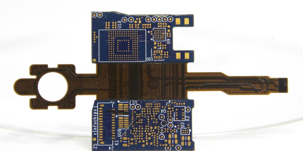
Rigid-Flex PCBs
Have both rigid and flexible substrates joined together in one circuit board. Rigid portions have layered fiberglass.
Flexible PCB Materials
Many materials are used in the fabrication of FPCBs. Some key materials include:
Polyimide
A thermoset plastic with excellent heat resistance, chemical resistance and mechanical strength. The most common FPCB substrate. Brand names include Kapton, Apical, UPILEX. 25μm to 75μm thickness.
Polyester
A thinner, more economical substrate material. Withstands flexing but has lower temperature resistance. Brand names like Melinex or Teonex. 12μm to 50μm thickness.
Liquid Crystal Polymer (LCP)
An advanced substrate with outstanding electrical performance and RF signal transmission. Expensive but used in high-frequency applications. Brand names such as Vectra or Zenite. 50μm to 100μm thickness.
Copper Foil
Used to form the conductive traces and pads. Rolled annealed copper with an electrodeposited treatment for adhesion. Available in 12μm to 70μm thickness.
Manufacturing Process of Flexible PCBs
- Design – Create PCB design files based on circuit requirements using CAD software.
- Film Lamination – Laminate copper foil onto the flexible substrate using heat and adhesive.
- Imaging – Photosensitive dry film is applied and imaged with UV light through a mask.
- Etching – Ferric chloride solution etches away unwanted copper, leaving behind traces.
- Stripping – Dry film is stripped away, leaving finished copper traces.
- Solder Mask – Liquid photoimageable solder mask (LPSM) is applied for insulation.
- Hot Air Solder Leveling – Tin-lead solder applied to exposed pads for easy component soldering.
- Electrical Testing – Boards are electrically tested for defects using fixtures.
- Assembly – Components are soldered onto contact fingers at the board edge.
- Quality Inspection – Finished boards are visually inspected to check for defects.
Typical Applications of Flexible PCBs
Thanks to their beneficial properties, flexible PCBs are used in a wide range of products and industries:
- Consumer Electronics – Mobile phones, laptops, cameras, wearables, VR headsets
- Computing – Printers, storage devices, modems, display screens
- Automotive – Instrument panels, LED lighting, door modules, infotainment systems
- Medical – Hearing aids, lab equipment, surgical devices, medical patches
- Industrial – Factory automation, robotics, control systems
- Military/Aerospace – Missiles, avionics, radar systems, antennas
- Internet of Things – Flexible sensors, wearable devices, smart electronics
Here are some examples of flexible PCBs used in specific products:
| Product | Use of Flexible PCB |
|---|---|
| Mobile phones | Wrapped around hinged flip phone to connect display to mainboard. Allows folding action. |
| Wearable devices | Conforms to curves of body and clothing. Maintains connectivity despite movement. |
| Hard disk drives | Connects arm actuator that positions read/write head over spinning platter. |
| Printer ink cartridges | Folds tightly to fit small cartridge form factor. Connects print nozzles. |
| Robot arms | Maintains connections for electronics through repeated articulated movements. |
| Smart clothing | Integrated into clothing to create e-textiles with lighting or sensors. |
| Automotive sensors | Withstands vibrations and ambient temperatures extremes in vehicle. |
Design Considerations for Flexible PCBs
Designing reliable flexible PCBs requires paying special attention to:
- Bend radius – Avoid sharp folds. Use generous bend radius of at least 10X material thickness.
- Flexibility – Position components for minimum flexing. Avoid folding through component bodies.
- Layer stackup – Stagger the ends of stiffeners and covers to prevent stiff spots.
- Adhesives – Use flexible, temperature resistant adhesives suitable for materials.
- Reinforcement – Add stiffeners or covers at stress points like connectors or buttons.
- Trace widths/spacing – Use larger trace sizes to increase durability. Allow for flexibility.
- Vias – Support vias appropriately to prevent cracks under dynamic bending.
- Connections – Allow sufficient flexing clearance around plated through holes.
- Creep resistance – Polyimide films provide better creep resistance than polyester.
- ESD/EMI – Include ground planes or traces between layers to shield signals.
Careful design is key to creating durable flex circuits that can survive repeated flexing without failure.
Flexible PCB vs Rigid PCB Comparison
Here is a comparison between key characteristics of flexible PCBs vs traditional rigid PCBs:
| Parameter | Flexible PCB | Rigid PCB |
|---|---|---|
| Substrate Material | Polyimide, polyester films | FR-4 glass epoxy |
| Thickness | 25μm – 150μm | 1.6mm |
| Layers | 1-8 layers | Up to 36+ layers |
| Conductors | Copper foils | Copper foils |
| Dielectric Constant | 3.4-3.6 | 4.8 |
| Loss Tangent | 0.002-0.004 | 0.02 |
| Temperature Range | -65°C to 150°C | -40°C to 130°C |
| Flexibility | Can be bent and flexed repeatedly | Rigid, cannot bend |
| Weight | Lightweight | Relatively heavier |
| Reliability | Prone to flex cracks | Structurally rigid, reliable |
| Cost | Higher | Lower |
| Applications | Dynamic, high-flex, small form factors | General rigid boards |
Pros and Cons of Flexible PCBs
Pros:
- Extremely flexible and dynamic
- Lightweight and space saving
- Vibration and impact resistant
- Allows innovative packaging and design
- Maintains connections despite motion
- Can integrate rigid and flex regions
Cons:
- More expensive than rigid PCBs
- Limited in terms of circuit complexity
- Prone to cracks and fracturing with improper flex design
- Requires specialized design considerations
- Soldering can be challenging
- More limited heat dissipation vs rigid boards
Frequently Asked Questions About Flexible PCBs
Here are some common questions and answers about flexible printed circuit boards:
What are the most common applications of FPCBs?
The most common uses are in consumer electronics (mobile phones, laptops, wearables), automotive, aerospace, medical devices, industrial, and IoT products where flexibility, space savings and dynamic connections are required.
How many times can a flex PCB be flexed before failing?
With proper design, flex circuits can achieve hundreds of thousands to millions of flex cycles. Polyimide substrates provide the highest flex life over other materials.
Can components be mounted directly on flexible PCBs?
It’s generally not recommended. Components are usually mounted off-board and attached to contact fingers along the flex board edge. This avoids cracking under dynamic stresses.
What are some key design rules for flexible PCBs?
Maintain sufficient bend radius, provide strain relief at connections, use flexible adhesives, stagger stiffeners/covers, allow for thermal expansion, increase trace widths for durability.
How are components assembled with flexible circuits?
Soldering directly to traces can crack them. So surface mount pads are added along the board edge to allow easy hand soldering without flexing the main circuit itself.
How do costs compare between rigid and flex PCBs?
Flexible PCBs are generally more expensive due to specialized materials, more complex fabrication and lower production volumes. But they provide unique benefits over rigid technology.
Is it possible to integrate both rigid and flexible materials in one PCB?
Yes, so-called rigid-flex PCBs contain both rigid board sections and flexible circuits within a single assembly. This allows rigid support where needed while maintaining dynamic flex.
This covers the key points about flexible PCB technology. The unique properties of flex circuits open up exciting design and packaging options not possible with rigid boards alone. With careful design, flexible PCBs enable reliability and innovation across many electronics sectors and applications that require dynamic flexibility and motion.