

Introduction to Flexible PCBs
A flexible printed circuit board (flex PCB or flex circuit) is a type of printable circuitry that is made with flexible and durable materials. Unlike traditional rigid PCBs, flex circuits can bend and flex while still maintaining their electrical connectivity. This makes them ideal for applications where the PCB needs to move or conform to a shape, like in wearable devices, medical equipment, consumer electronics, automotive dashboards, and more.
Some key advantages of flexible PCBs include:
- Lightweight and thinner than rigid boards
- Can bend and flex without damage
- Good for dynamic flexing applications
- Can conform to 3D shapes
- Less prone to cracking than rigid boards
- Often created with flexible substrates like polyimide
Common uses for flex PCBs:
- Wearable devices
- Medical devices
- Consumer electronics
- Automotive electronics
- Robotics and UAVs
- IoT and sensors
Flex circuits allow complex circuitry to fit into tight or dynamic spaces that rigid boards cannot. They are growing in popularity as flexible electronics become more widespread across industries. However, assembling flex PCBs requires some different considerations compared to traditional PCB assembly.
Flexible PCB Assembly Process Overview
Assembling a flexible printed circuit board follows a similar assembly process as rigid PCBs, but has some unique requirements to handle the flexible material. Here is a general overview of the flexible PCB assembly process:
1. Design and Fabrication
The circuit design is created and fabricated on a thin, bendable substrate like polyimide. The number of layers can vary depending on complexity.
2. Component Attachment
Components are soldered or adhesive mounted onto the flex board. Care must be taken not to crack solder joints when flexing.
3. Stiffener Application
Rigid stiffeners may be added to aid assembly and protect components. Kapton tape is commonly used.
4. Connector Attachment
Connectors are added, either soldered or with conductive epoxy. Flex-friendly connectors are preferred.
5. Board Covering
Conformal coatings or protective layers are added to insulate and protect the flex circuitry.
6. Final Testing
The finished assembly is tested for functionality and durability with flexing/bending.
Throughout the assembly process, extra care must be taken when handling the thin, dynamic material of the flex circuit. Let’s look at some of the steps and considerations in more detail:
Flexible PCB Design
The circuit layout must be designed to handle flexing and dynamic bending. Here are some best practices:
- Use large pad sizes and clearances to avoid cracking
- Avoid 90 degree angles on traces
- Use tear-drop pad shapes to prevent trace breaks
- Minimize component density in bend areas
- Use cross-hatched ground planes for stability
- Allow for stretching and contraction of traces
- Lay out traces in the neutral bend axis where possible
Component Attachment
Attachments must be flexible and durable. Some methods include:
- Soldering: Requires flex-friendly solders and strain relief
- Conductive epoxy: Resilient, but lower conductivity
- Anisotropic tape: Tape that is z-axis conductive only
- Mechanical fasteners: Screws, rivets, etc. Requires pad reinforcement
Components may require flexible forms or casings, like urethane-coated parts. Rigid parts can fracture solder joints when flexing.
Stiffener Application
Adding stiffeners prevents flexing in select areas and aids assembly. Common materials:
- Kapton tape: Thin polyimide tape with acrylic adhesive
- Polyimide film: Bonded with acrylic adhesive during lamination
- Rigid-flex: Sections of rigid FR4 laminated with flex circuit
Stiffeners provide temporary stability for easier assembly, but are removed before flexing operation.
Connectors
Specialized flex connectors are made to handle constant flexing. Types include:
- Polyimide: Flexible Kapton connectors solder directly to traces
- Elastomeric: Conductive rubber connectors that compress vertically
- Zero insertion force (ZIF): Flexible connections without solder
- Buckling beam: Spring-loaded beams absorb flexing
Carefully align connectors during placement to prevent tearing or detachment.
Covering and Coatings
Protective coatings add insulation and durability:
- Conformal coatings: Thin lacquers like acrylic or silicone
- Polyimide laminate: Adhesive Kapton layers over components
- Glob top: Thick silicone deposit over components
Coverings prevent shorting, fractures, and environmental damage during flexing.
Flexible PCB Testing
Thoroughly test prototypes and finished circuits:
- Validate bend radius and flexion cycles
- Check for cracking solders, traces, substrates
- Confirm no opens or shorts when flexed
- Ensure proper adhesion with tape peel tests
- Validate component connections during motion
- Test connectors and mating cycles
By following these best practices during flexible PCB assembly, you can produce durable, reliable flex circuits capable of continuous flexing in their target applications. Careful design, component selection, protective covering, and testing helps ensure flexing performance.
Advantages and Disadvantages of Flexible PCBs
Let’s compare some of the key pros and cons of using flexible PCBs versus traditional rigid boards:
Advantages
- Can conform to 3D shapes and spaces
- Thinner, lighter, and more compact
- Bendable and shapeable
- Tolerant of flexion and repeated bends
- Less prone to cracking than rigid boards
- Allows dynamic component placement
- Good for high vibration environments
- Reduces wiring and assembly needs
Disadvantages
- More expensive than rigid PCBs
- Limited in overall size
- Lower component density
- Requires specialized assembly methods
- Prone to tearing if mishandled
- Maximum layer count around 12 layers
- Traces can fatigue and crack over time
- Requires compatible components and connectors
Flex circuits excel in applications where tight space, movement, vibration, and conformability are critical requirements. The ability to dynamically place components in three dimensions can justify the higher assembly costs in complex designs. For very dense, multilayered circuits, rigid PCBs are still preferred when flexibility is not required.
Applications and Examples of Flexible Printed Circuit Boards
To see flexible PCBs in action, let’s look at some real-world applications and examples:
Wearable Electronics
- Fitness trackers
- Smart watches
- Smart clothing
- Medical sensors
- Augmented reality glasses
Wearables need to bend, flex, and contour to the human body, so rigid boards are unpractical. Flex circuits can wrap around wrists and arms smoothly.
Consumer Electronics
- Cell phones
- Laptops and tablets
- Digital cameras
- Game controllers
- Video displays
Many consumer devices have tight, crowded internals. Flex circuits fold neatly around other components and help reduce product size.
Automotive Electronics
- Touch sensors on steering wheels
- Circuitry in car seats
- Video displays in dashboards
- Controls on center consoles
- Circuits in sunroofs and doors
Vehicles subject boards to vibrations and space constraints. Flex circuits conform to curved surfaces and withstand vibration better than rigid boards.
Medical Equipment
- Hearing aids
- ICU sensors and wires
- X-ray components
- Endoscopes and probes
- Implantable devices
Medical devices must be biocompatible and often miniaturized. Flexible boards work well in body-worn, handheld, and internal applications.
Robotics and UAVs
- Joints and appendages
- Landing gear and arms
- Payload interfaces
- Structural sensors
- Motor controllers
Robots and drones can flex and move dynamically. Flex circuits allow electronic connections to safely stay intact during motion.
For these and many other applications, flexible circuit boards provide the perfect connectivity solution when the PCB can’t be completely rigid. As flex PCB technology improves and costs decrease, usage should continue expanding across industries that value miniaturized, dynamic circuits.
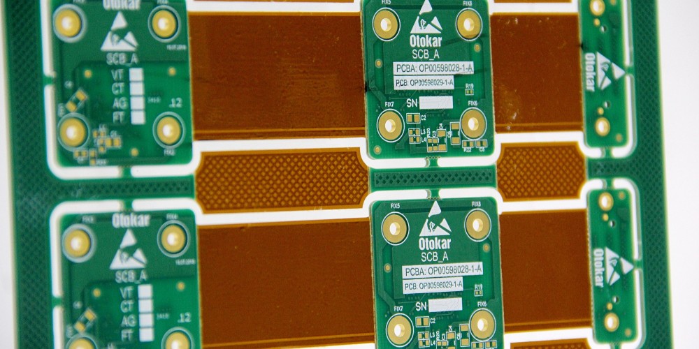
Flexible vs Rigid-Flex PCBs
There is an important distinction between pure flexible PCBs and rigid-flex boards. Here is a quick comparison:
Flexible PCB
- Entirely bendable circuit material
- Typically polyimide substrate
- Can be rolled, folded, twisted, etc.
- No sections remain permanently rigid
- Dynamic freedom of movement
Rigid-Flex PCB
- Combines rigid board sections with flex circuit sections
- Rigid parts made of typical FR4 substrate
- Flexible “hinges” connect the rigid areas
- Limited dynamic movement at flex junctions
- Folding or rolling is segmental only
With rigid-flex boards, manufacturers can get the benefits of standard PCBs and flex circuits in one design. Rigid sections offer component density and multilayering, while flexible portions enable necessary movement and 3D assembly. Products like laptops and mobile phones often utilize rigid-flex PCBs.
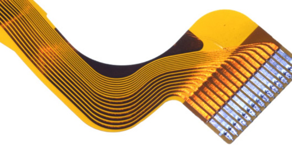
Flexible PCB Materials
The substrate material is what gives flex PCBs their flexibility. While rigid boards use glass reinforced FR-4, flex circuits use specially engineered flexible polymers. Here are some common flex circuit substrate materials:
Polyimide (Kapton)
- Most common flex substrate
- Highly heat and chemical resistant
- Withstands temperatures up to 400°C
- Typical thickness around 0.05mm
Polyester (PET)
- Often used in low-cost consumer electronics
- Not as heat resistant as polyimide
- More economical alternative
- Shrinks slightly during soldering
Polyethylene Naphthalate (PEN)
- High temperature resistance (up to 200°C)
- Low moisture absorption
- Good dimensional stability
- Used for circuits exposed to moisture
Fluoropolymers (PTFE)
- Excellent chemical resistance
- Withstands very high temperatures
- Low surface friction
- Relatively expensive
Liquid Crystal Polymer (LCP)
- Extremely heat resistant (300°C+)
- Low moisture absorption
- Withstands flexing and twists
- Common in miniaturized devices
The substrate directly affects the flex life, temperature resistance, chemical immunity, and cost of the PCB. Polyimide is the most proven and versatile, but materials like LCP and PEN also have niche benefits.
Flexible vs Rigid PCB Cost Differences
In general, flexible PCBs have a higher cost per unit area compared to their rigid counterparts. Here are some typical cost differences:<div class=”md-table md-typeset”>
| PCB Type | Cost per Square Inch |
|---|---|
| Rigid PCB | $5 – $15 per in<sup>2</sup> |
| Flex PCB | $15 – $30 per in<sup>2</sup> |
</div>
Reasons flexible PCBs cost more include:
- Specialized flexible substrate materials
- Additional chemical/mechanical processing
- Lower fabrication yields
- More manual assembly steps
- Specialized components and connectors
- Lower overall production quantities
However, for complex assemblies, flex circuits can reduce overall product cost by:
- Simplifying wiring harnesses and cabling
- Lowering component counts
- Reducing manual soldering steps
- Enabling tighter, smaller product packaging
- Improving manufacturing automation
As flex PCB production volume increases and processes improve, costs continue to come down gradually. But for now, the specialized materials and processes involved in flex circuit fabrication keep their costs moderately higher than standard rigid boards.
Quality Control and Testing Flexible PCBs
Verifying the reliability of a flex PCB requires testing both the base materials and the fully assembled board. Here are some typical quality control and testing procedures:
Substrate Material Testing
- Adhesion: Test bond strength of copper foil to substrate
- Flexibility: Validate minimum bend radius without damage
- Wear: Check for substrate abrasion during repeated flexions
- Environmental: Exposure to temperatures, humidity, fluids
Assembled Board Testing
- Interconnects: Confirm no opens or shorts during flexion
- Solder joints: No cracking during repeated bends
- Components: Verify parts stay attached during motion
- Coatings: Test coverage and adhesion using tape peel test
- Electrical: Continuity testing and function validation
- Life cycle: Simulate total flexion cycles of real-world use
The completed flex assemblies should go through vibration, mechanical shock, and long duration environmental testing. This ensures the materials, attachments, and coatings can withstand the application demands.
Flexible PCB Design Software
Specialized PCB design software is needed to properly layout and model flex circuits. Here are some popular options:
- Altium Designer – Industry-leading PCB design platform with integrated flex and rigid-flex capabilities.
- Cadence Allegro – Full-featured engineering design suite with solutions for flex and rigid-flex boards.
- Mentor Graphics Xpedition – Sophisticated electronics design platform with flex circuit modeling and simulation.
- Eagle CAD – More affordable PCB design tool with flex capabilities. Part of Autodesk suite.
- OrCAD – Flex circuit layout solution that integrates with Allegro PCB Editor.
- SolidWorks – 3D engineering modeling software with growing circuit design functionality.
Advanced flex board software allows for dynamic bend radius rules, flex and rigid section definitions, and detailed visualization of flexing. This helps optimize routability and clearances while ensuring the design can actually be manufactured.
Applications that Benefit from Flexible PCBs
Here are some major applications and product categories that often utilize flexible PCB technology:
Consumer Electronics
Laptops, tablets, mobile phones, cameras, wearables, game controllers, displays
Medical Equipment
Pacemakers, hearing aids, implants, sensors, catheters, endoscopes
Automotive Electronics
Touch sensors, control units, lighting, in-car displays
Robotics
Arms, joints, end effectors, structural health sensors
Industrial
Niche instruments, testers, scanners, measurement devices
Aerospace
UAVs, fuselage sensors, astronaut suits, structural monitors
Military
Wearables, helmet devices, sensors, communications
Internet of Things
Flexible sensor nodes, connectors, wearables
Any product that needs squeeze into tight spaces, contour and bend, or withstand dynamic motion can benefit from flex PCB technology. As conductive ink printing improves, flexible circuits will enable even more innovative applications across industries.
Future Outlook for Flexible PCBs
The flexible PCB market is poised for robust growth in the coming decade. Here are some projections on the future of flex circuit boards:
- Global market to grow 8% CAGR to $27 billion by 2028
- Asia Pacific currently leads market share at 61%
- Automotive and medical sectors will drive adoption
- Improved fabrication automation will increase capacity
- Development of flex PCB-based antennas
- Flexible hybrid electronics integration will rise
- Conductive nano inks will enable additive printing
- Higher layer counts and finer traces
With technology trends toward wearables, sensors, displays, and flexible hybrid electronics, flex circuits will continue playing a critical role in product miniaturization and functional integration. As manufacturing improves, costs decrease, and more applications require dynamic movement, flexible PCB prevalence and value will continue accelerating.
Conclusion
Flexible printed circuit boards enable electronics to bend, twist, and integrate into extremely compact spaces. They are vital in products where packaging, contours, vibrations, and repeated movements demand thin, light, and resilient circuitry. With strong growth forecast across automotive, medical, consumer electronics, and other industries, flexible PCB technology will continue advancing hand-in-hand with the wearables and sensors of the future. Companies need specialized flex design software and assembly processes to take advantage of these capabilities in their products. By following the latest trends and best practices in flex circuit fabrication and assembly, engineers can implement the next generation of flexible hybrid electronics.
Flexible PCB Frequently Asked Questions
Here are some common FAQs about flexible printed circuit boards:
What are the main advantages of flexible PCBs?
Flex PCBs main advantages are: conformability to shapes, bendability, vibration resistance, lightweight/thinness, and ability to integrate compactly into products. They allow complex dynamic motions that rigid boards cannot.
What are some typical applications for flex circuits?
Typical flex PCB applications: wearables, medical devices, consumer electronics, automotive dashboards, robotics, UAVs, and Internet of Things products. Any dynamic or tight space environments.
How do costs compare between rigid and flexible PCBs?
Flexible PCBs are typically 2-5x more expensive per unit area than rigid boards. Reasons include specialized materials, lower production volumes, and more manual assembly. Prices range $15-$30/in2 for flex vs $5-$15 for rigid.
What are some good flexible PCB substrate materials?
Common flex PCB substrate materials are: polyimide (Kapton), PET, PEN, fluoropolymers like PTFE, and liquid crystal polymers (LCP). Polyimide is the most popular and cost-effective generally.
How many layers can flex PCBs support?
While rigid boards can have dozens of layers, flex PCBs typically max out around 12 layers. Some high-end flex can reach 20 layers, but any more causes fabrication difficulties with the flexible polymers.
Can flex PCBs have rigid sections too?
Yes, rigid-flex PCBs combine flexible circuit sections with rigid board areas. This allows high component density while