

Overview of the PCB Manufacture Process
The PCB manufacture process can be broadly divided into the following stages:
- PCB Design and Layout
- PCB Fabrication
- Substrate Preparation
- Copper Cladding
- Drilling
- Plating
- Etching
- Solder Mask Application
- Silkscreen Printing
- PCB Assembly
- Component Placement
- Soldering
- Inspection and Testing
- Quality Control and Testing
PCB Design and Layout
The first step in the PCB manufacture process is the design and layout of the circuit board. This stage involves creating a schematic diagram that represents the electrical connections and components of the circuit. The schematic is then used to develop a layout, which determines the physical placement of components and traces on the board.
PCB design software, such as Altium Designer, Eagle, or KiCad, is used to create the schematic and layout. The designer must consider various factors, including:
- Component selection and placement
- Trace width and spacing
- Power and ground planes
- Signal integrity and electromagnetic compatibility
- Manufacturing constraints and design rules
Once the design is finalized, the layout files are generated in a format compatible with the PCB fabrication process, such as Gerber or ODB++.
PCB Fabrication
The PCB fabrication stage involves the physical creation of the circuit board. This stage consists of several sub-processes, each contributing to the final product.
Substrate Preparation
The substrate, typically made of FR-4 (a glass-reinforced epoxy laminate), is the foundation of the PCB. The substrate is cut to the desired size and shape using precise machinery. Cleaning and surface preparation are performed to ensure proper adhesion of the copper layer.
Copper Cladding
A thin layer of copper is bonded to one or both sides of the substrate using a process called electroless copper deposition. This layer serves as the conductive material for the traces and pads on the PCB.
Drilling
Holes are drilled through the substrate to accommodate through-hole components and create vias for inter-layer connections. Drill files generated from the PCB layout are used to guide the drilling machines, ensuring accurate placement and sizes of the holes.
Plating
After drilling, the holes are plated with copper to create electrical connections between layers. This process, known as electroplating, involves depositing a layer of copper onto the walls of the drilled holes, ensuring continuity and conductivity.
Etching
The unwanted copper areas on the PCB are removed through a process called etching. A photoresist layer is applied to the copper surface and exposed to UV light through a photomask, which contains the desired trace and pad patterns. The exposed areas of the photoresist are then developed and removed, leaving the copper exposed in those areas.
The board is then immersed in an etching solution, typically ferric chloride or ammonium persulfate, which removes the exposed copper, leaving only the desired traces and pads intact.
Solder Mask Application
A solder mask, usually green in color, is applied to the PCB surface to protect the copper traces from oxidation and prevent solder bridges during the assembly process. The solder mask also provides electrical insulation between adjacent traces and pads.
The solder mask is applied as a liquid photoimageable coating and then exposed to UV light through a photomask, which defines the areas where the solder mask should remain. The unexposed areas are then developed and removed, leaving the desired solder mask pattern on the board.
Silkscreen Printing
The final step in the PCB fabrication process is silkscreen printing. This process involves applying text, logos, and component identifiers onto the PCB surface using a silkscreen and ink. The silkscreen printing assists in the assembly process and provides a professional appearance to the finished product.
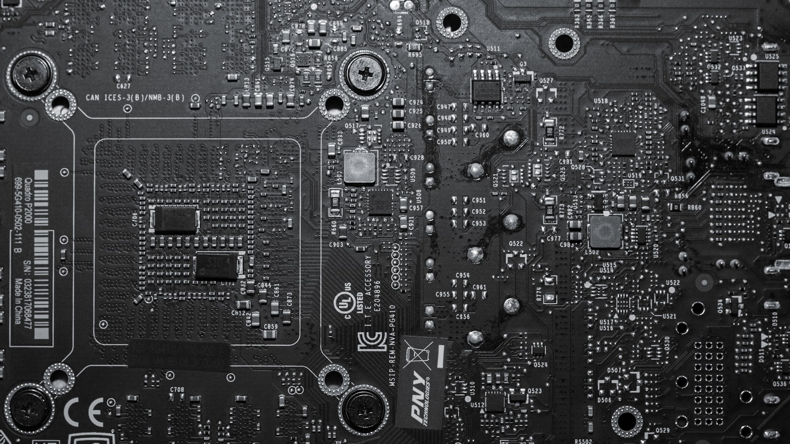
PCB Assembly
Once the fabrication process is complete, the PCB moves to the assembly stage, where electronic components are attached to the board.
Component Placement
Surface mount components are placed onto the PCB using pick-and-place machines. These machines use computer-aided design (CAD) files to accurately position the components on the designated pads. Through-hole components are inserted manually or using automated insertion machines.
Soldering
After component placement, the PCB undergoes a soldering process to establish electrical connections between the components and the board. Two primary soldering methods are used:
-
Wave Soldering: The PCB is passed over a molten solder wave, which contacts the bottom side of the board and creates solder joints on the through-hole components.
-
Reflow Soldering: A solder paste, containing tiny solder spheres mixed with flux, is applied to the PCB pads using a stencil. The board is then heated in a reflow oven, causing the solder to melt and form connections between the components and pads.
Inspection and Testing
After soldering, the assembled PCB undergoes visual inspection and automated optical inspection (AOI) to detect any soldering defects, component misalignments, or missing components. Electrical testing, such as in-circuit testing (ICT) or functional testing, is performed to ensure the proper functioning of the assembled board.
Quality Control and Testing
Throughout the PCB manufacture process, various quality control measures are implemented to ensure the reliability and performance of the final product. These measures include:
- Incoming material inspection
- Process control and monitoring
- Automated optical inspection (AOI)
- X-ray inspection for hidden solder joints
- Electrical testing (e.g., continuity, insulation resistance, and high-potential testing)
- Functional testing
- Environmental testing (e.g., temperature, humidity, and vibration)
- Burn-in testing to identify early failures
By adhering to strict quality control standards and testing procedures, PCB manufacturers can deliver high-quality, reliable circuit boards that meet the requirements of various industries and applications.
Advancements in PCB Manufacturing
The PCB manufacturing industry continuously evolves to keep pace with the increasing complexity and miniaturization of electronic devices. Some notable advancements in PCB manufacturing include:
High-Density Interconnect (HDI) PCBs
HDI PCBs feature finer trace widths, smaller vias, and higher component density compared to traditional PCBs. These advancements enable the creation of compact, high-performance electronic devices, such as smartphones, tablets, and wearables.
Multilayer PCBs
Multilayer PCBs consist of multiple layers of conductive material separated by insulating layers. This construction allows for more complex routing and higher component density, enabling the development of advanced electronic systems.
Flexible and Rigid-Flex PCBs
Flexible PCBs are made using thin, flexible substrate materials, such as polyimide, which allows the board to bend and conform to various shapes. Rigid-flex PCBs combine the benefits of both rigid and flexible substrates, enabling the creation of three-dimensional electronic assemblies with improved reliability and space savings.
Embedded Components
Embedded component technology involves placing passive components, such as resistors and capacitors, inside the PCB substrate. This approach reduces the overall board size, improves signal integrity, and enhances the performance of high-frequency circuits.
3D Printing for PCB Prototyping
3D printing technology has been adapted for PCB prototyping, enabling rapid and cost-effective creation of functional circuit boards. Conductive and insulating materials are deposited layer by layer to form the PCB structure, allowing for quick iterations and design validation.

Environmental Considerations in PCB Manufacturing
As environmental awareness grows, the PCB manufacturing industry has taken steps to adopt more sustainable and eco-friendly practices. Some key environmental considerations include:
Lead-Free Soldering
The Restriction of Hazardous Substances (RoHS) directive has driven the adoption of lead-free soldering in PCB manufacturing. Lead-free solder alloys, such as tin-silver-copper (SAC), have replaced traditional lead-based solders, reducing the environmental impact of electronic waste.
Halogen-Free Materials
Halogen-free PCB materials, such as halogen-free flame retardants (HFFRs), are being increasingly used to minimize the release of toxic substances during the manufacturing process and end-of-life disposal.
Green Manufacturing Processes
PCB manufacturers are implementing green manufacturing practices to reduce energy consumption, minimize waste, and optimize resource utilization. This includes the use of renewable energy sources, closed-loop water systems, and recycling of materials.
Recycling and E-Waste Management
Proper recycling and disposal of electronic waste (e-waste) are essential to mitigate the environmental impact of PCBs. Many PCB manufacturers have established recycling programs and partnerships to ensure the responsible handling of end-of-life products.
Frequently Asked Questions (FAQ)
-
What is the difference between surface mount and through-hole components?
Surface mount components are mounted directly onto the surface of the PCB, while through-hole components have leads that are inserted into holes drilled through the board and soldered on the opposite side. -
What is the purpose of solder mask on a PCB?
The solder mask is a protective coating applied to the PCB surface that prevents solder bridges between adjacent traces and pads, provides electrical insulation, and protects the copper traces from oxidation. -
What is the role of a PCB design software in the manufacturing process?
PCB design software is used to create the schematic diagram and layout of the circuit board. It helps designers optimize component placement, trace routing, and ensure compliance with manufacturing constraints and design rules. -
How do manufacturers ensure the quality and reliability of PCBs?
PCB manufacturers implement various quality control measures, including incoming material inspection, process control, automated optical inspection (AOI), electrical testing, and environmental testing to ensure the quality and reliability of the final product. -
What are some of the environmental considerations in PCB manufacturing?
Key environmental considerations in PCB manufacturing include the use of lead-free soldering, halogen-free materials, green manufacturing processes, and proper recycling and disposal of electronic waste.
Conclusion
The PCB manufacture process is a complex and multi-faceted endeavor that requires precision, expertise, and adherence to strict quality standards. From the initial design and layout to the final assembly and testing, each stage of the process plays a crucial role in creating reliable and high-performance circuit boards.
As the electronics industry continues to evolve, PCB manufacturing techniques and technologies must keep pace to meet the demands of increasingly complex and compact devices. Advancements such as HDI PCBs, multilayer boards, flexible and rigid-flex PCBs, embedded components, and 3D printing are reshaping the landscape of PCB manufacturing.
Moreover, the industry is increasingly focusing on environmental sustainability, adopting practices such as lead-free soldering, halogen-free materials, green manufacturing processes, and responsible e-waste management.
By understanding the intricacies of the PCB manufacture process and staying informed about the latest developments and best practices, designers, engineers, and manufacturers can collaborate effectively to create innovative, reliable, and environmentally-friendly electronic products that shape our world.