


Introduction
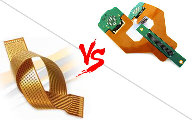
Printed circuit boards (PCBs) are essential components of most modern electronic devices. There are several types of PCBs, with two major categories being rigid PCBs and flexible PCBs (flex PCBs). Within flex PCBs, there are sub-categories like rigid-flex PCBs and semi-flex PCBs. This article will examine the key differences between rigid-flex and semi-flex PCBs.
Rigid-Flex PCBs
Rigid-flex PCBs, also known as flex-rigid PCBs, are composed of rigid PCB sections interconnected by flexible PCB sections. They provide a combination of the stability and structural integrity of a rigid PCB with the flexibility and motion capabilities of a flex PCB.
Construction
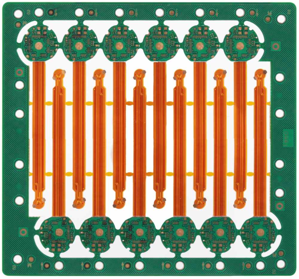
Rigid-flex PCBs contain both rigid board layers and flexible layers laminated together into a single structure. The rigid sections are typically made of traditional PCB substrate materials like FR-4, while the flex sections use a polyimide film substrate.
Here are some key construction elements:
- Rigid layers – Made of FR-4 or other rigid material. Provide structure and stability.
- Flexible layers – Made of polyimide. Allow bending and flexing.
- Adhesive layers – Bond the rigid and flex layers.
- Cover layers – Protect outer surfaces. Can be rigid or flexible.
- Stiffeners – Additional rigid sections to strengthen specific areas.
Properties
Rigid-flex PCBs offer a hybrid set of properties by combining rigid and flex:
- Structural stability from rigid sections
- Flexibility and bendability from flex sections
- Ability to fold and wrap around structures
- Dynamic flexing and repeated bending
- Compatibility with high density interconnects
- Good thermal performance
Applications
Due to their unique combination of rigidity and flexibility, rigid-flex PCBs are used in many applications:
- Consumer electronics – Cell phones, laptops, cameras
- Automotive – Dashboard electronics, engine control units
- Medical – Hearing aids, wearable monitors
- Military – Guided missiles, avionics systems
- Industrial – Robotics, machine controllers
Any application requiring both stability and movable interconnections can benefit from rigid-flex PCBs. The rigid sections provide mounting stability and component sites, while the flex sections enable movement and three-dimensional configuration.
Semi-Flex PCBs
Semi-flex PCBs have a blend of rigid and flexible characteristics, but without distinct rigid and flex sections within the same board. The entire board has some degree of bendability and flex capability.
Construction
Semi-flex PCBs are made using substrates that are flexible to a certain degree. They are typically single-layer or two-layer boards. Some common semi-flex constructions:
- FR-4 material with thinner dielectrics (~0.3 mm). More flexible than standard 1.6 mm FR-4.
- Polyimide substrates. Can be one-sided, two-sided, or multilayer.
- Thermoplastic liquid crystal polymer (LCP). Provides moderate flex strength.
- Metal core substrates with polyimide dielectrics. Good thermal and bend properties.
They may also include stiffeners in select areas to limit bending.
Properties
The properties of semi-flex PCBs include:
- Moderate flex strength. Can bend but not as easily as pure flex PCBs.
- Able to dynamically flex to a certain degree.
- More rigid than pure flex PCBs. Provide some structural stability.
- Typically not as mechanically durable as rigid-flex PCBs over repeated bending.
- Cost advantage over rigid-flex. Simpler manufacturing process.
Applications
Semi-flex PCBs are a lower cost option when some flex capability is needed without the complexity of rigid-flex PCBs. Example applications:
- LED lighting
- Medical sensors
- Industrial controls
- Consumer devices
- Wearable electronics
Any application where a simple one or two layer circuit needs moderate bendability can utilize a semi-flex board.
Key Differences Between Rigid-Flex and Semi-Flex
Here is a comparison summary of some of the key differences:
| Parameter | Rigid-Flex PCB | Semi-Flex PCB |
|---|---|---|
| Construction | Multiple layers with distinct rigid and flexible sections | Typically 1-2 layers without distinct sections |
| Flexibility | Very flexible in flex areas | Moderately flexible overall |
| Rigidity | Very rigid in rigid areas | Moderate rigidity overall |
| Bend radius | Tight in flex areas | Wider overall |
| Thermal performance | Very good in rigid areas | Moderate overall |
| Complexity | More complex, multi-stage manufacturing | Simpler manufacturing |
| Cost | Higher | Lower |
| Reliability | Very durable over bending cycles | Moderate bend cycle life |
| Example applications | Cell phones, guided missiles | LED lights, wearable sensors |
In summary:
- Rigid-flex PCBs provide areas of both rigidity and flexibility in a single board.
- Semi-flex PCBs have moderate flexibility over the entire board area.
- Rigid-flex PCBs are more complex and expensive but can achieve 3D configurations.
- Semi-flex PCBs are simpler and lower cost for basic flex applications.
Manufacturing Processes
The manufacturing processes for rigid-flex and semi-flex PCBs have some differences:
Rigid-Flex PCB Fabrication
Rigid-flex PCBs require specialized fabrication that laminates the rigid and flex layers together:
- Rigid layers fabricated separately using standard PCB processes
- Flex layers fabricated separately on polyimide
- Materials bonded in a laminated multi-stage process
- Careful alignment of layers and registration
- Controlled bend radius for flex areas
- Often involves manual assembly
The process is complex and requires advanced equipment to precisely align layers and create the sharp transitions between rigid and flex areas.
Semi-Flex PCB Fabrication
Semi-flex PCB fabrication is simpler, using processes similar to standard PCBs:
- Single- or double-sided boards on flexible substrate
- Conventional PCB fabrication lines
- Same etching, masking, plating steps
- Fewer lamination stages
- Do not require special rigid-flex equipment
The semi-flex manufacturing process is lower cost, but does not allow distinct rigid and flex sections within the same board.
Cost Considerations
Due to the manufacturing differences, rigid-flex PCBs are inherently more expensive than semi-flex:
- Rigid-flex materials cost more
- Multi-stage lamination increases costs
- Lower yields and more scrap
- Specialized equipment and manual steps
- Testing and inspection overhang
- Higher design costs
Here is a rough comparison of costs:
| PCB Type | Typical Cost |
|---|---|
| Rigid Flex | $500 – $5,000 per square foot |
| Semi-Flex | $50 – $500 per square foot |
However, rigid-flex PCBs enable advanced configurations that cannot be achieved with semi-flex. The additional costs may be justified for performance benefits in complex designs.
Design Considerations
Both rigid-flex and semi-flex PCBs require special design considerations:
Rigid-Flex Design
- Careful planning of layer stackup
- Partitioning of rigid and flex sections
- Minimizing rigid-to-flex transitions
- Bend radius control
- Stress relief features at transitions
- Flex and rigid component placement
- Thermal managementacross sections
- Dynamic bend cycle analysis
Semi-Flex Design
- Selecting appropriate flexible substrate
- Component placement for bending
- Controlling flexing areas with stiffeners
- Managing thermal stresses from bending
- Providing strain relief for traces
- Analysis of bend cycles and fatigue
Both design processes are more complex than for standard rigid PCBs. Rigid-flex design involves additional factors with the layer transitions.
Summary of Key Differences
In summary, the key differences between rigid-flex PCBs and semi-flex PCBs are:
- Rigid-flex uses distinct rigid and flexible sections, while semi-flex bends overall
- Rigid-flex is more mechanically durable over bend cycles
- Rigid-flex enables advanced 3D configurations not possible with semi-flex
- Semi-flex provides a lower cost option when simple bending is needed
- Rigid-flex has specialized manufacturing processes, while semi-flex uses standard PCB fabrication
- Rigid-flex design requires management of rigid-flex transitions
For applications requiring flexible and rigid regions, and maximum ruggedness, rigid-flex PCBs are the best choice. When cost is critical, and only modest bendability is needed, semi-flex can be a viable option. Carefully evaluating the application requirements and trade-offs between the two technologies is important in selecting the optimal PCB design.
Frequently Asked Questions
Here are some common FAQs about rigid-flex and semi-flex PCBs:
Q: Can components be mounted directly on flexible sections?
A: Yes, both rigid-flex and semi-flex PCBs allow components to be mounted directly on flexible areas. The component and solder joint design must account for the dynamic bending to avoid cracks or failure.
Q: How many bend cycles can rigid-flex PCBs withstand?
A: Rigid-flex PCBs are typically tested for 500+ dynamic bend cycles for 90 degree bends. More dramatic bending has lower cycle lifetimes. Careful design is needed to avoid flex failures.
Q: Can semi-flex PCBs achieve the same 3D configurations as rigid-flex?
A: No, semi-flex boards are limited in the 3D shapes they can conform to compared to rigid-flex. The mixture of rigid and flex sections gives rigid-flex superior shaping capabilities.
Q: What are the main reliability risks for semi-flex PCBs?
A: Trace cracking, solder joint failure, and delamination are main failure modes for semi-flex PCBs over repeated bending. Careful strain relief, trace design, and testing helps improve reliability.
Q: What types of connectors are used on rigid-flex and semi-flex PCBs?
A: Flexible connectors or soldered wire joints are options for connecting to rigid-flex or semi-flex PCBs in bending applications. Rigid connectors can be used in rigid regions or with strain relief.
Conclusion
Rigid-flex PCBs and semi-flex PCBs both provide solutions for applications needing bendable and flexible circuits. Rigid-flex PCBs offer the highest performance with distinct rigid and flexible regions, while semi-flex provides a simpler, lower cost design. By understanding the trade-offs, electrical engineers can select the optimal flex PCB technology for their specific application requirements. Careful design, simulation, prototyping, and testing is crucial to implement either rigid-flex or semi-flex PCBs successfully.