Introduction to PCBs
A printed circuit board, or PCB, is the foundation of nearly all modern electronic devices. Whether it’s a smartphone, laptop, TV, or even a microwave, chances are it contains at least one PCB. But what exactly is a PCB and how does it work? In this comprehensive PCB Guide for beginners, we’ll cover everything you need to know about these essential components.
What is a PCB?
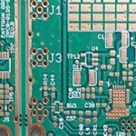
A PCB is a flat board made of insulating materials like fiberglass, with conductive copper traces printed onto it in a specific pattern. These copper traces connect various points on the board, allowing electricity to flow between electronic components like resistors, capacitors, and integrated circuits (ICs) that are soldered onto the board.
PCBs provide a compact and reliable way to assemble and connect electronic components. Before PCBs, circuits were constructed through point-to-point wiring, which was time-consuming, error-prone, and resulted in bulky devices. PCBs solved these issues by providing a stable platform for components with pre-defined connections.
Types of PCBs
There are several types of PCBs, each with its own unique characteristics and manufacturing process. The most common types include:
| PCB Type | Layers | Application |
|---|---|---|
| Single-sided | 1 | Simple, low-cost devices |
| Double-sided | 2 | Improved connectivity, increased complexity |
| Multi-layer | 3+ | High-density, complex devices |
| Flexible | Varies | Wearables, compact devices |
| Rigid-Flex | Varies | Combines rigid and flexible sections |
- Single-sided PCBs: These boards have conductive traces on only one side, with components soldered on the opposite side. They are the simplest and most cost-effective option but are limited in terms of component density and connectivity.
- Double-sided PCBs: These boards have conductive traces on both sides, allowing for more complex circuits and better connectivity between components. Holes drilled through the board, called vias, enable connections between the two sides.
- Multi-layer PCBs: These boards consist of three or more layers of conductive traces, separated by insulating layers. They offer the highest component density and complexity but are also the most expensive to manufacture.
- Flexible PCBs: These boards are made from flexible materials, allowing them to bend and conform to various shapes. They are often used in wearables and other compact devices.
- Rigid-Flex PCBs: These boards combine rigid and flexible sections, offering the benefits of both types in a single board.
PCB Manufacturing Process
The PCB manufacturing process involves several steps, each of which is critical to ensuring the quality and reliability of the final product.
Step 1: Design
The first step in creating a PCB is to design the circuit schematic and board layout using specialized software like Altium Designer, Eagle, or KiCad. The schematic defines the electrical connections between components, while the board layout determines their physical placement on the PCB.
Step 2: Printing
Once the design is finalized, the PCB layout is printed onto a transparent film called a photomask. This film is used to transfer the circuit pattern onto the copper-clad board in the next step.
Step 3: Etching
The copper-clad board is coated with a light-sensitive chemical called a photoresist. The photomask is then placed on top of the board and exposed to UV light. The areas of the photoresist that are exposed to light become soluble and can be washed away, leaving behind the desired copper traces.
The board is then placed in an etching solution, which removes the unwanted copper, leaving only the circuit pattern.
Step 4: Drilling
Holes are drilled into the board to accommodate through-hole components and to create vias for multi-layer boards. The drilling process is typically automated using computer-controlled machines.
Step 5: Plating
For double-sided and multi-layer boards, the holes are plated with copper to create electrical connections between layers. This process involves applying a thin layer of copper to the entire board and then removing the unwanted copper using another photoresist and etching process.
Step 6: Solder Mask and Silkscreen
A solder mask, usually green in color, is applied to the board to protect the copper traces from oxidation and to prevent solder bridges between closely spaced components. A silkscreen layer is then added to provide labels, logos, and other markings on the board.
Step 7: Surface Finish
The exposed copper areas, such as component pads and test points, are coated with a protective finish to prevent oxidation and improve solderability. Common surface finishes include:
- Hot Air Solder Leveling (HASL)
- Organic Solderability Preservative (OSP)
- Electroless Nickel Immersion Gold (ENIG)
- Immersion Silver
- Immersion Tin
Step 8: Electrical Testing
Before the components are soldered onto the board, the PCB undergoes electrical testing to ensure that all connections are correct and that there are no short circuits or open connections. This process is called a “bare board test.”
Step 9: Component Assembly
Finally, the electronic components are soldered onto the PCB using either through-hole or surface-mount technology (SMT). Through-hole components have long leads that are inserted into holes drilled in the board and soldered on the opposite side. SMT components are smaller and are soldered directly onto the surface of the board.
PCB Design Considerations
When designing a PCB, there are several key factors to consider to ensure optimal performance, reliability, and manufacturability.
Component Placement
Proper component placement is crucial for several reasons:
- Signal Integrity: Components should be placed to minimize the length of critical signal paths, reduce crosstalk, and maintain proper impedance matching.
- Thermal Management: High-power components should be spaced apart and located near the board edges to facilitate heat dissipation.
- Manufacturing: Components should be oriented and spaced to allow for automated assembly and to minimize the risk of solder bridges.
Trace Width and Spacing
The width and spacing of copper traces on a PCB depend on several factors, including:
- Current Carrying Capacity: Traces carrying high currents must be wider to prevent overheating and to minimize voltage drop.
- Impedance Control: Traces carrying high-speed signals must have controlled impedance to minimize reflections and signal distortion.
- Manufacturing Constraints: Trace width and spacing must meet the minimum requirements of the PCB manufacturer to ensure reliability and yield.
Power and Ground Planes
Multi-layer PCBs often include dedicated power and ground planes to provide low-impedance power distribution and to minimize noise. These planes also serve as a reference for controlled impedance traces and help to reduce electromagnetic interference (EMI).
Via Placement
Vias are used to connect traces on different layers of a multi-layer PCB. Via placement should be optimized to:
- Minimize signal path length
- Reduce via-to-via coupling
- Avoid blocking critical signal paths
- Facilitate manufacturing and assembly
Design for Manufacturing (DFM)
To ensure that a PCB can be manufactured reliably and cost-effectively, designers must adhere to the manufacturing constraints and guidelines provided by the PCB fabricator. These constraints include minimum trace width and spacing, minimum hole size, and minimum clearance between components and board edges.

PCB Testing and Inspection
After the PCB is manufactured and assembled, it must undergo various tests and inspections to ensure that it meets the required quality standards and performs as intended.
Visual Inspection
The first step in PCB testing is a visual inspection to check for any obvious defects or assembly issues, such as:
- Solder bridges or cold solder joints
- Missing or misaligned components
- Damaged or lifted pads
- Incorrect component orientation
Automated Optical Inspection (AOI)
AOI is a computer-based inspection method that uses cameras and image processing algorithms to detect assembly defects. AOI systems can quickly identify issues like missing components, incorrect component placement, and solder defects.
X-Ray Inspection
X-ray inspection is used to detect defects that are not visible on the surface of the board, such as:
- Voids in solder joints
- Bridging between ball grid array (BGA) connections
- Broken wire bonds in chip packages
In-Circuit Testing (ICT)
ICT is a test method that uses a bed-of-nails fixture to make electrical contact with specific points on the PCB. The fixture applies electrical signals and measures the response to verify that the board is assembled correctly and that all components are functioning as intended.
Functional Testing
Functional testing involves powering up the PCB and verifying that it performs its intended function. This may include testing the board’s response to various inputs, measuring output signals, and checking for any intermittent or temperature-dependent issues.
PCB Assembly Techniques
There are two primary methods for assembling components onto a PCB: through-hole and surface-mount technology.
Through-Hole Technology
Through-hole components have long leads that are inserted into holes drilled in the PCB and soldered on the opposite side. This assembly method is older and less common than SMT but is still used for certain components like connectors, large capacitors, and transformers.
Advantages of through-hole technology include:
- Stronger mechanical connections
- Easier to replace or repair components
- Better for high-power or high-voltage applications
Disadvantages include:
- Larger component size and board space requirements
- Higher assembly costs and slower production rates
- Limited component density compared to SMT
Surface-Mount Technology (SMT)
SMT components are smaller and are soldered directly onto the surface of the PCB. This assembly method has largely replaced through-hole technology in modern electronics due to its many advantages:
- Smaller component size and higher component density
- Faster assembly rates and lower production costs
- Improved high-frequency performance
However, SMT also has some disadvantages:
- More difficult to replace or repair components
- Requires specialized assembly equipment and processes
- More susceptible to thermal and mechanical stress
Mixed Assembly
Some PCBs use a combination of through-hole and SMT components, known as mixed assembly. This approach allows designers to take advantage of the benefits of both technologies while minimizing their drawbacks.
PCB Materials and Substrates
The choice of PCB material and substrate is critical to the board’s performance, reliability, and cost. The most common PCB substrate materials include:
FR-4
FR-4 is a glass-reinforced epoxy laminate that is the most widely used PCB substrate material. It offers a good balance of mechanical, electrical, and thermal properties at a relatively low cost. FR-4 is suitable for most general-purpose applications but may not be optimal for high-frequency or high-temperature environments.
High-Frequency Laminates
For applications involving high-frequency signals, such as RF and microwave circuits, specialized laminate materials are used to minimize signal loss and distortion. These materials, such as Rogers RO4000 series and Isola IS680, have lower dielectric constants and dissipation factors compared to FR-4.
Metal Core PCBs
Metal core PCBs (MCPCBs) use a metal substrate, typically aluminum, to enhance heat dissipation in high-power applications. The metal core is coated with a thin layer of dielectric material, onto which the copper traces are laminated. MCPCBs are commonly used in LED lighting, power electronics, and automotive applications.
Flexible Substrates
Flexible PCBs use thin, flexible substrates like polyimide or polyester to allow the board to bend and conform to various shapes. These materials offer high strength, stability, and resistance to heat and chemicals. Flexible substrates are used in applications where space is limited, or the board must flex during use, such as in wearables, medical devices, and aerospace equipment.
PCB Design Software and Tools
To design and layout PCBs, engineers use specialized software tools that offer schematic capture, board layout, and design rule checking (DRC) capabilities. Some popular PCB design software packages include:
- Altium Designer
- Autodesk Eagle
- KiCad
- Cadence Allegro
- Mentor Graphics PADS
These tools allow designers to create schematics, define component footprints, route traces, and generate manufacturing files like Gerber and drill files. They also include libraries of pre-made components and footprints to streamline the design process.
Many PCB design tools also offer simulation and analysis features to help optimize signal integrity, power distribution, and thermal performance. These features can help identify and correct issues before the board is manufactured, reducing the risk of costly redesigns and production delays.
Frequently Asked Questions (FAQ)
What is the difference between a PCB and a printed wiring board (PWB)?
PCB and PWB are often used interchangeably, but there is a slight difference in their definitions. A PCB is a general term for a board with printed conductive traces and components, while a PWB specifically refers to a board with only printed wires and no mounted components. In practice, most people use the term PCB to refer to both types of boards.
Can I design and manufacture my own PCBs at home?
Yes, it is possible to design and manufacture simple PCBs at home using a process called the toner transfer method. This involves printing the PCB layout onto a special transfer paper using a laser printer, ironing the design onto a copper-clad board, and then etching away the unwanted copper. However, this method is limited in terms of precision, reliability, and the complexity of the circuits that can be produced.
For more advanced PCBs, it is recommended to use a professional PCB fabrication service. These services offer high-quality manufacturing, a wide range of materials and finishes, and the ability to produce complex multi-layer boards.
What is the typical turnaround time for PCB manufacturing?
The turnaround time for PCB manufacturing depends on several factors, including the complexity of the design, the chosen materials and finishes, and the manufacturer’s workload. For simple, 2-layer PCBs, turnaround times can be as short as 24-48 hours. For more complex, multi-layer boards, turnaround times can range from several days to a few weeks.
Many PCB manufacturers offer expedited services for an additional fee, which can significantly reduce the turnaround time. It’s important to work closely with your chosen manufacturer to understand their capabilities and to plan your project timeline accordingly.
How much does it cost to manufacture a PCB?
The cost of PCB manufacturing depends on several factors, including:
- Board size and complexity
- Number of layers
- Materials and finishes
- Quantity ordered
- Turnaround time
For small quantities (1-100) of simple, 2-layer PCBs, prices can range from a few dollars to a few tens of dollars per board. For larger quantities or more complex boards, prices can range from a few hundred to several thousand dollars.
To get accurate pricing for your specific project, it’s best to request quotes from several PCB manufacturers. Many manufacturers offer online quoting tools that allow you to upload your design files and receive instant price estimates.
What are the most common PCB Design Mistakes to avoid?
Some of the most common PCB design mistakes include:
- Incorrect component footprints or orientations
- Violating manufacturer’s design rules (e.g., minimum trace width or spacing)
- Poor signal integrity (e.g., crosstalk, reflections, or ground loops)
- Insufficient power or ground connections
- Inadequate thermal management
- Lack of proper testing and prototyping
To avoid these mistakes, it’s important to follow best practices for PCB design, work closely with your manufacturer, and thoroughly test and validate your designs before committing to production. Many PCB design software tools also include design rule checking (DRC) features that can help identify and correct common design errors.
Conclusion
PCBs are the backbone of modern electronics, enabling the creation of compact, reliable, and high-performance devices. By understanding the basics of PCB design, manufacturing, and assembly, engineers and hobbyists can create custom circuits that meet their specific needs and requirements.
This comprehensive guide has covered the essential topics related to PCBs, including their types, manufacturing process, design considerations, testing and inspection methods, assembly techniques, materials and substrates, and design software and tools. It has also addressed some of the most frequently asked questions about PCBs.
Whether you are a beginner looking to learn more about PCBs or an experienced designer seeking to expand your knowledge, this guide provides a solid foundation for understanding and working with these critical components. As with any complex topic, there is always more to learn, but by mastering the fundamentals covered here, you will be well-equipped to tackle your next PCB project with confidence.


