What are the connectors in PCB?
Introduction to PCB connectors
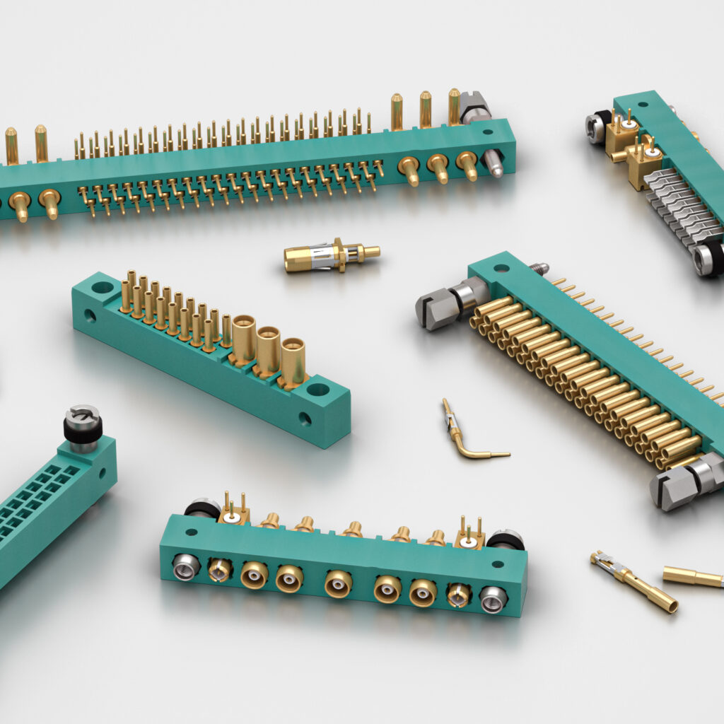
A printed circuit board (PCB) relies on connectors to transfer signals and power between the board and external devices or systems. Connectors act as the interface that allows a PCB to communicate and interact with the rest of an electronic product.

There are many different types of connectors that serve various purposes in PCB design. Board connectors provide:
- Power supply – Connectors supply power from a power source to the PCB.
- Data transfer – They allow transfer of data signals to and from the PCB through cables and wires.
- Interconnection – Connectors enable connection between the PCB and other system components or PCBs.
- User interaction – Connectors that allow user interaction and control such as ports, buttons, switches etc.
Choosing the right connector involves factors like signal types, data transfer speed, frequency, retention force, polarity, cost, reliability, ease of assembly etc.
Types of PCB connectors
There are various types of connectors designed to handle different signals, frequencies, data speeds and interfaces. Here are the major categories:
Header connectors
Pin header connectors
Pin headers refer simple connector types designed for insertion into corresponding female sockets or receptacles. They consist of a single or double row of pins enclosed in a plastic housing. They are polarized and may contain 3 to over 100 pins. Common examples include:
- Male header pins
- Female socket headers
- Straight pin headers
- Right angle pin headers
They are low cost, easy to assemble and replace. Pin alignment can affect signal integrity at high frequencies above 10GHz. Popular interfaces using pin header connectors include USB, HDMI, Ethernet and GPIO.
Pin header connector (Image credit: Mouser Electronics)
Terminal block connectors
Terminal blocks provide temporary scaffolding to connect wires and test circuit operation. Screw terminal blocks allow wires to be securely fastened while maintaining connection. They are often used for signal splitting and branching. Terminal blocks are available in wide array of sizes, shapes and pin counts. They allow fast prototyping through easy installation without soldering. However maximum current capacity is limited to 15-20 Amps.
6-way terminal block connector (Image credit: Mouser Electronics)
Board-to-board connectors
These connectors provide reliable interconnect solutions between PCBs or from a PCB to other system units. Different types are:
Board stacking connectors
Board stacking connectors allow multiple PCBs to be vertically stacked together maintaining alignment and connectivity. They provide strong robust mechanical coupling between boards along with high density signal transition. Popular stacking connectors are:
- PCI express connectors – Designed for perpendicular stacking of PCBs using PCIe data bus. Provides very high data transfer rates upto 32 Gbps across up to 16 lanes.
- MEZZANINE connectors – Allows parallel attachment of a mezzanine PCB card to a main base board. Signal integrity is maintained at high speeds between CPU and peripheral devices.
Mezzanine board-to-board stacking connector (Image credit: Arrow)
Board-to-FPC connectors
These connectors allow reliable interface between a rigid printed circuit board and a flexible printed circuit (FPC) or flat flexible cable (FFCs). Zero insertion force (ZIF) connectors provide precision aligned connections to FPC/FFCs that can withstand thousands of mating cycles. They are used to interconnect devices like cameras, motors, displays, etc requiring flexible circuitry to the main PCB.
FPC connector (Image credit: Mouser Electronics)
Board-to-wire connectors
They enable easy termination of individual wires to specific tracks on a PCB. They eliminate the need to solder cable wires directly. Screw terminals allow secure wire fastening. Different configurations are available including single row or dual-row wire-to-board connectors based on applications.
I/O connectors
These external connectors are used to interface the PCB with external devices, peripherals, cables or other systems allowing input or output of signals. Some common types are:
USB connectors
Universal Serial Bus (USB) connectors enable connection of peripherals like mouse, keyboard, hard drives, audio devices, etc to the USB port on the PCB. Standard USB sizes used are USB-A, USB-B, USB-C and Mini/Micro versions. Latest USB 4.0 & Thunderbolt allow speeds up to 40 Gbps.

USB connector types (Image credit: Bulgin)
HDMI connectors
HDMI (High Definition Multimedia Interface) connectors are used for uncompressed transmission of high quality audio/video data from devices like DVD players to video displays like TV screens with resolution up to 4K. Type A, Type B, Type C, Type D and Micro HDMI versions are available.
Ethernet connectors
These connectors are used to connect devices like computers, modems and switches in local area networks and provide high speed gigabit data transmission up to large distances through RJ45 interface via Category 5e or 6 twisted pair Ethernet cables.
RF connectors
Coaxial RF connectors are used for transmission of radio frequency signals above 20KHz and microwaves up to 40 GHz in applications like antenna feeds, WiFi, satellite TVs over coaxial cables offering protection from interference. RF connectors used are SMA, SMB, SMC, SSMT, TNC, etc. Cable television uses F connectors.
PCB connector attributes
Choosing PCB connectors requires evaluating parameters like:
Number of contacts
It indicates the connector’s signal carrying capacity or circuit size it can accommodate. Number of contacts available go upto several hundred pins for complex interconnection requirements.
Pitch
It specifies pin spacing or distance between connector contacts, important for compatibility and signal integrity in high speed signals upto 10 Gbps and higher. Pitch for header connectors range from 0.1, 0.2 inches to 2.54mm or higher for RF connectors.
Current rating
Rated current for a connector indicates how much current it can continuously carry per circuit safely. It affects power distribution and good connector selection ensures reliable performance under temperature extremes meeting regulatory standards.
Contact termination technique
It denotes how connector contacts interface with the PCB – using surface mount pads or plated thru-holes. SMT consumes less space while thru hole pins offer stronger mechanical attachment to board.
Contact type
Pin connectors use solid conductor pins while socket connectors employ receptacle contacts. Two plug contact types are:
- Stamped contacts – Cheaper, comprise thin strips of beryllium copper alloy stamped into shape. Used for transferring power or lower speed signals.
- Machined contacts – Made of rods of beryllium copper machined to shape to achieve springy property. More expensive but sustain signal integrity at higher frequencies.
Durability
Connectors must handle frequent matings like medical diagnostic equipment or withstand vibrations. Durability is ensured through gold, nickel plating; robust housing and quality contact material selection rated for thousands of mechanical insertions.
Environmental sealing
Connectors must prevent moisture, water spray, dust ingress through protective shells with rubber gaskets for shielding in harsh environments.
Choosing right PCB connectors
Connector selection requires assessment of critical performance factors as shown in table:
| Connector | Features | Applications |
|---|---|---|
| PCB Headers | Inexpensive, horizontal/vertical, single/double row, through-hole/SMT contacts up to 20 Amps, 64 contacts, pitch options 0.1 – 2.54 mm | Prototyping connections to 0.5A devices |
| Board Stacking | High density signal routing across stacked PCBs, up to 32 Gbps speeds via PCIe, power currents over 150 Amps via busbars | Server blade architectures, peripheral interfaces |
| FPC Connectors | Compact, durable, 5000 mating lifecycles, pitch 0.3-1.27mm | Interfacing flat flex cables in consumer goods |
| USB Connectors | Supports USB4 speeds upto 40Gbps, extended power delivery upto 240W, reversible plug orientation | Mouse, keyboard, HDD peripherals |
| HDMI Connectors | Resolutions upto 4K@120Hz, backward compatibility, speeds upto 48Gbps | Ultra HD Displays and TV connections |
| Ethernet Connectors | Fast Ethernet/Gigabit data speeds, integral magnetics, robust metal housing | Networking equipment connections |
| RF Connectors | Weatherproof, extended frequency ranges upto 120 GHz, low passive intermodulation | Microwave radio systems, cellphone towers |
Table summarizing connector selection criteria based on application
Apart from electrical & frequency characteristics, additional factors influencing choice of appropriate connectors include:
- Cost considerations
- Size constraints
- Assembly methods
- Environmental operating conditions
- Compliance requirements
Understanding application needs and priorities guides designers toward right connector selection ensuring reliable performance. Using quality connectors from reputed manufactures like TE Connectivity, Molex, Hirose, Bulgin or Samtec also minimizes field failures.
PCB connector design considerations

To guarantee optimum connector performance, some aspects require attention during design:
Signal integrity
For high speed applications over 10 Gbps, factors causing signal degradation are:
- Excess inductance and capacitance
- Impedance discontinuities
- Cross talk
- Electromagnetic interference at higher frequencies
This requires judicious connector pin-out arrangements, adequate grounding and shielding techniques.
Power handling
Connectors must reliably sustain power currents drawn by today’s high performance ICs and modules. This demands larger conductor cross-section, employing more pins in parallel to share current. High temperature rated materials ensure stable contact resistance when hot.
Layout considerations
Connector location on PCB influences size constraints, routing congestion and EMI radiation. Keeping connectors along board edges saves space while minimizing track lengths, vias improves signal trace impedance control.
Ease of assembly
Connectors must facilitate simple visual inspection, manual alignment/attachment using integral board locks, catch mechanisms without requiring additional brackets. Automated assembly may need polarized shrouded connectors preventing misalignment.
Reliability testing
Environmental stress screening through temperature cycling, shock, vibration and durability tests must validate connector design performance over product lifecycle enabling process improvements.
Conclusion
Connectors satisfy critical interconnect needs in PCBs allowing interface to the application environment. Connector selection entails complex trade-offs between electrical characteristics, mechanical construction, size, assembly methods and cost based on signal types and application demands. Understanding connector properties and design considerations enables building robust interface solutions ensuring reliable system performance and long operational life.
Frequently Asked Questions
Q1. Why are connectors important in PCB?
Connectors enable a PCB to input and output signals and power, interact with peripheral devices, other PCB assemblies, cables and overall system electronics. They facilitate seamless communication and expandability acting as bridges to the external environment. Connectors impact reliability, cost and ease of field servicing.
Q2. What are backplane connectors?
Backplane connectors establish interconnection between PCB cards plugged into a common backplane or motherboard in industrial computer architectures needing high density cabling across large boards spanning cabinets. They allow hot swapping of cards enabling upgrades. High pin counts exceeding 400 pins provide massive data bandwidth across PCBs. Examples include PICMG, VME64x, CompactPCI and proprietary form factors.
Q3. How are connectors mounted onto a PCB?
Common PCB mounting configurations are:
- Through-hole – Connector pins pass through holes in board fixed using solder, suitable for thicker boards
- Surface mount – Connector pads sit on top of copper tracks on board and soldered, saves space in dense boards
Additional strengthening uses board locks, L shaped legs or captive screws.
Q4. What are criteria for connector insertion orientation?
Connector orientation means direction along which mating happens through male-female interlocking ensuring:
- Proper pin alignment avoiding damage
- Polarization preventing incorrect insertion
- Mechanical stability with integral board locks
- Ergonomic accessibility for cables
Connectors have vertical or 90/180 degree horizontal orientation options. Shrouds prevent misalignment.
Q5. How is contact reliability tested in connectors?
Contacts experience failures through fretting corrosion, temperature rise or loss of elasticity. Reliability screening applies accelerated test cycles simulating extreme temperature, humidity, vibration, thermal shocks over thousands of insertion cycles checking contact resistance or insulator breakdown. Tests establish Mean Time Between Failure (MTBF) rates for connectors as quality benchmarks.


