


Rigid-flex PCBs, also known as flex-rigid PCBs, combine rigid PCBs and flexible PCBs into one interconnected design. These circuit boards provide the benefits of both rigid boards and flexible circuits in a single solution. Rigid-flex PCBs allow designers to integrate rigid and flexible substrates in 3-dimensional configurations that would not be possible with a fully rigid board.
What are Rigid-Flex PCBs?
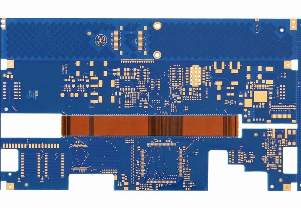
A rigid-flex PCB consists of rigid sections interconnected by flexible circuits. The rigid portions provide mechanical support and leverage surface mount and through-hole technologies, while the flexible circuits enable three-dimensional configurations and dynamic flexing. By combining both rigid and flexible materials, rigid-flex PCBs offer many advantages over single-substrate boards.
Rigid-flex PCBs consist of layers of conductive copper traces laminated between insulating dielectric substrate layers. The dielectric substrate used in the rigid sections is typically FR-4 or polyimide, while the flexible sections use polyimide or polyester materials. The layers are bonded together using adhesive layers or thermal bonding processes. Rigid-flex PCBs can have traces and components mounted on either side of the board. They may also incorporate blind and buried vias to interconnect layers and rigid-flex sections.
Benefits of Rigid-Flex PCBs
Here are some of the key benefits that rigid-flex PCBs provide:
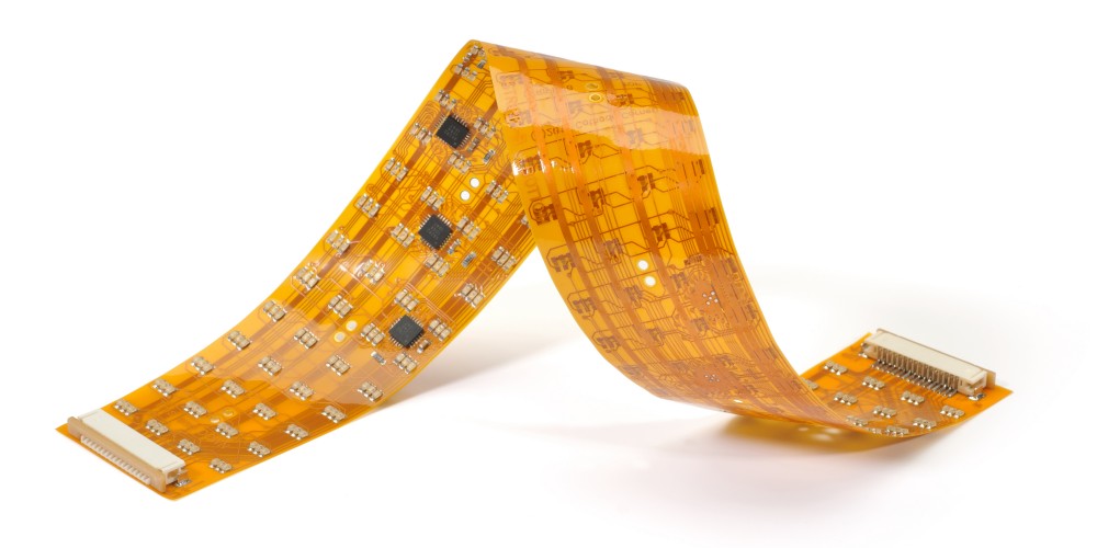
- Complex and compact 3D configurations: Rigid-flex PCBs allow for complex geometries and 3-dimensional folding that enables more compact product designs. The flex circuits provide dynamic bending and folding while maintaining electrical connections between rigid sections.
- Reduced weight and size: By replacing wires and connectors, rigid-flex PCBs allow for reduced system weight and size. The need for separate rigid PCBs and interconnects is eliminated.
- Increased reliability: Rigid-flex PCBs have fewer interconnections than using separate rigid and flex circuits. The reduced contact points and solder joints improve reliability and product life.
- Improved high-speed performance: The continuous interconnects of rigid-flex PCBs provide uninterrupted transmission line paths for high-speed signals. This improves signal integrity compared to traditional discrete wiring.
- Enhanced vibration durability: The flexible sections of rigid-flex PCBs absorb stresses from shock, vibration, and flexing that would damage soldered connections. This improves reliability in high vibration environments.
- Simplified assembly: By combining rigid and flex circuits into one assembly, rigid-flex PCBs simplify manufacturing and reduce assembly cost and time. Handling and aligning discrete circuits during assembly is eliminated.
Comparison of Rigid-Flex and Rigid PCB Characteristics
| Parameter | Rigid PCB | Rigid-Flex PCB |
|---|---|---|
| Layer Count | Typically ≤ 28 layers | Typically ≤ 12 layers |
| Dielectric Material | FR-4, Polyimide | Combination of FR-4, Polyimide, Polyester |
| Copper Thickness | 1-2 oz. typical | 1 oz. typical |
| Minimum Line/Space | 3/3 mil | 5/5 mil typical |
| Vias | Small annular rings, many vias | Large annular rings, fewer vias |
| Flexibility | Very rigid | Dynamic flexing and folding |
| Weight | Heavier | Lighter |
| Interconnects | Connectors, wires | Integrated traces |
| Reliability | Solder joint failures | Improved stress tolerance |
| Design Complexity | Simpler | Complex geometries |
Rigid-Flex PCB Applications
Rigid-flex PCBs are well-suited for many applications, especially in space constrained and high reliability products. Here are some examples of where rigid-flex PCBs provide design advantages:
Aerospace and Military
- Missiles and avionics equipment
- UAVs, drones, and robotics
- Radios, antennas, and radar systems
- Engine control systems
- Armored vehicle electronics
The high reliability and durability of rigid-flex PCBs makes them suitable for the extreme environments seen in aerospace and military applications. The ability to condense electronics into smaller and lighter assemblies is also beneficial.
Medical Equipment
- Hearing aids
- Wearable patient monitors
- Implantable devices
- Ultrasound transducers
- Dental cameras
Medical products must balance patient comfort and ergonomics with electronics capabilities. Rigid-flex PCBs allow for compact, lightweight assemblies with dynamic flexing to improve patient wearability and access to tight spaces.
Consumer Electronics
- Cell phones
- Laptops and tablets
- Digital cameras
- Wearables and smart watches
- Virtual reality headsets
As consumer electronics become more powerful and feature-rich, rigid-flex PCBs allow designers to fit more functionality into ever smaller packages. The folding and compact stacking capabilities are ideal for the small packages required.
Automotive Electronics
- Drive control units
- Safety systems (airbags)
- Entertainment consoles
- Navigation and instrument clusters
- Lighting modules
- Engine control modules
Rigid-flex PCBs withstand automotive shock and vibration requirements while enabling condensed electronics assemblies. Complex 3D geometries are used to fit electronics around other components under the hood and dashboard.
Rigid-Flex PCB Design Considerations
Designing rigid-flex PCBs requires special considerations for the combination of rigid and flex materials in one assembly. Here are some of the important design factors:
- Layer stackup: Must account for differences in rigid and flex dielectrics and ensure proper adhesion between sections.
- Routing: Avoid sharp flex bends. Distribute traces to balance loads. Allow for dynamic flexing.
- Component placement: Ensure components are only on rigid sections and avoid placing on folds.
- Vias: Use large annular rings for reliability. Limit vias on flex areas and avoid overlapping rigid-flex junctions.
- Thermal management: Heat dissipation must be considered both on rigid and flex areas.
- Testing: Allow for both rigid and flexing conditions during functional testing.
Proper rigid-flex PCB design requires specialized constraints and verification checks compared with standard rigid PCBs. Working with a manufacturer experienced in rigid-flex fabrication is highly recommended to ensure manufacturability and reliability are achieved.
Frequently Asked Questions About Rigid-Flex PCBs
Here are some common questions about rigid-flex PCB technology:
What are the typical layers used in rigid-flex PCBs?
The rigid sections of the PCB typically use standard FR-4 dielectric which provides better thermal and mechanical stability for components and vias. The flexible sections use polyimide or polyester films which enable repeated dynamic flexing. Total layer counts are usually 6, 8, or 10 to balance flexibility with interconnect needs.
Can components be mounted on both sides of rigid-flex PCBs?
Yes, components can be surface mounted on both sides of the rigid portions, and potentially on single sided flex areas. Double sided flex component mounting is challenging due to the thin flexible material. Rigid sections provide the stability needed for double sided assembly.
How are components interconnected between separate rigid sections?
The flexible circuits provide continuously connected traces between components on individual rigid segments. This eliminates the need for separate wires or connectors between sections. Components on separate rigid areas can interconnect just as if they are on a single contiguous board.
How durable are the dynamic flex areas?
When properly designed, the flexible areas can survive millions of bend cycles without failure. Typical flex materials like polyimide and polyester can withstand rolling and unfolding motions throughout the product’s lifetime. Proper trace spacing, limited vias, and bend radii avoid concentration of stresses.
How are rigid-flex PCBs tested and inspected?
Rigid-flex PCBs require specialized test fixtures to support the combination of rigid and dynamic flexible areas. Flying probe and fixture based testers contain movable plates and hinges that can hold the board while allowing the flex areas to bend and flex during in-circuit testing. Automated optical inspection systems also have advanced capabilities to inspect rigid flex PCB assemblies.
Conclusion
Rigid-flex PCBs provide an ideal solution whenever conventional rigid boards and separate flex circuits won’t suffice. By combining the advantages of both technologies into one assembly, rigid-flex PCBs offer size and weight reduction, improved reliability, simplified assembly, enhanced performance, and design flexibility. With an experienced manufacturer providing design and fabrication expertise, rigid-flex PCBs enable electronics packages that would be difficult or impossible to achieve with alternative approaches. As products continue getting smaller and more powerful, rigid-flex PCBs will take on an increasingly important role with unlimited possibilities for innovation.