


Introduction to Rigid Flex PCBs
Flexible printed circuits (FPCs) have revolutionized the electronics industry by allowing circuitry to be bent and flexed to fit into tight spaces. Rigid-flex PCBs take this a step further by combining rigid PCB materials with flexible circuits. This allows rigid sections to provide structure and support while flexible sections enable connections between components that move.
Rigid-flex PCBs provide the best of both worlds – the precision and reliability of rigid boards combined with the dynamic flexibility of flex circuits. In this article, we’ll explore what rigid-flex PCBs are, their benefits, design considerations, and various applications.
What Are Rigid Flex PCBs?
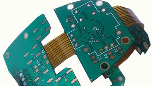
A rigid-flex PCB consists of both rigid and flexible substrate materials laminated together into a single circuit board. The rigid sections provide mechanical support and enable high component density, while the flexible sections allow dynamic flexing and 3D routing between components.
Here are the key elements of a rigid-flex PCB:
- Rigid sections – Made from typical PCB substrate material like FR-4. Provide structure and support.
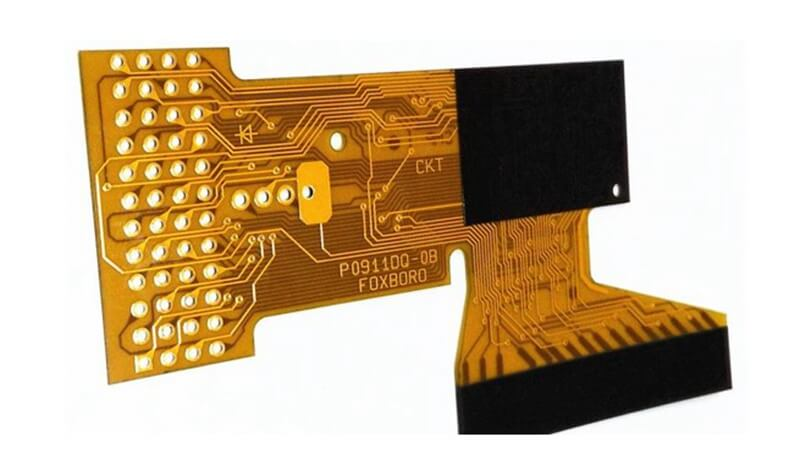
- Flexible sections – Made from polyimide or other flexible polymer. Allow bending and flexing.
- Coverlay – Polyimide overlay that protects conductors on flex sections.
- Bonded layers – Rigid and flex layers bonded using adhesive films.
Rigid-flex PCBs come in many configurations. Some have multiple rigid sections connected by flexible sections, allowing the board to fold and bend. Others have a single main rigid section with flexible leads extending off it. Some rigid-flex boards can flex dynamically during use, while others are folded once during assembly.
Benefits of Rigid Flex Circuits
Rigid-flex PCBs provide unique advantages over using separate rigid PCBs and flex circuits:
- Space savings – By combining rigid and flex materials, rigid-flex PCBs optimize space much better than separate components.
- Flexibility – Dynamic flexing allows movement between components on a single board.
- Reliability – Integrated connectivity reduces interconnections between separate boards.
- Weight savings – Thin flexible materials reduce weight compared to rigid-only designs.
- Layer integration – Rigid and flex sections can share layer stackup for simpler design.
- Assembled interconnects – Components can be assembled directly onto the rigid-flex PCB.
- Cost savings – Fewer boards and connectors can significantly reduce costs.
In many applications, rigid-flex PCBs are the ideal solution, offering properties that neither rigid nor flex PCBs can achieve alone. The ability to integrate rigid and flex materials into a single circuit enables electronics that are more compact, lightweight, dynamic, and reliable.
Design Considerations for Rigid Flex
Designing a successful rigid-flex PCB requires special considerations for the combination of rigid and flex materials into a single board. Here are some of the most important design factors:
Layer Stackup
The rigid and flex sections can share a common layer stackup, which simplifies design vs. separate PCBs and flex circuits. However, care must be taken with how layers transition between the rigid and flex areas.
Bend Radii
Flexible sections must be designed with sufficient bend radius to avoid damaging conductors on the inner bend layers. Typically 3-4X the board thickness. Dynamic flexing needs larger radii.
Transitions
Special handling is needed where the rigid and flex layers are joined. Polyimide stiffeners may be used to prevent unwanted bending stress.
Bonds
Adhesive bonds between the layers must be designed to withstand mechanical stress between areas with different stiffness.
Reinforcements
Cutouts and edge plating may be used selectively in flex areas to provide mechanical stability where needed.
Component Placement
Components in rigid sections can use normal SMT assembly. Flex section components require special adhesives and handling.
With good communication between the designer and manufacturer, these considerations can be handled appropriately to produce a reliable, high-quality rigid-flex board.
Applications of Rigid Flex Circuits
Rigid-flex PCBs enable solutions for a diverse range of products and industries. Here are some examples of rigid-flex applications:
Consumer Electronics
- Cell phones
- Laptops
- Digital cameras
- Wearables
- Game controllers
Medical
- Imaging systems
- Surgical tools
- Implants
- Hearing aids
Automotive
- Engine control units
- Dash displays
- Blind spot detection
- Lighting
Industrial
- Robotics
- Sensors
- HMI displays
- Precision instruments
Military/Aerospace
- Guidance systems
- UAVs and drones
- Soldier-worn electronics
- Satellites
In these and many other applications, rigid-flex PCBs deliver interconnectivity, reliability, and compact flexibility beyond the capabilities of rigid or flex PCBs individually.
Rigid Flex PCB Materials
There are a variety of materials used in rigid-flex PCB construction. Here are some of the most common:
Rigid Substrates
- FR-4 – Most common rigid PCB material
- High-temp FR-4 – For boards requiring higher temperature rating
- Polyimide – An alternative rigid substrate material
- Aluminum – Can be used when high stiffness needed
Flexible Dielectrics
- Polyimide – Used for flex layers. Available in various thicknesses.
- PEEK – A high temperature thermoplastic polymer.
- LCP – Liquid crystal polymer. Used for its chemical resistance.
- PET – Polyethylene terephthalate. Lower cost but less flexible.
Bonded Layers
- Acrylic – Common adhesive to bond layers. Many grades available.
- Epoxy – Can also be used to bond rigid/flex layers.
Coverlay
- Liquid photoimageable – Applied as a coating then processed like soldermask.
- Adhesive polyimide film – Bonded on top of flex conductors.
The combination of materials can be optimized based on mechanical, electrical, and reliability requirements.
Rigid Flex PCB Manufacturing
Producing a reliable rigid-flex board requires specialized fabrication techniques. Here is an overview of the rigid-flex manufacturing process:
- Sheets of the rigid and flexible materials are prepared.
- Holes are punched in the rigid sections.
- Conductors are etched on the individual layers.
- Layers are strategically bonded using adhesive films.
- Registration holes align the layers during lamination.
- Bonded layers are laminated under heat and pressure.
- Board is routed to shape with special handling at rigid/flex transitions.
- Conductors are tested for continuity defects.
- Components are assembled onto the board.
- Final testing validates proper function.
Rigid-flex manufacturing requires expertise in handling and bonding a variety of specialized materials. Work with a manufacturer experienced in producing quality rigid-flex PCBs.
Rigid Flex PCB Design Guidelines
Here are some key guidelines to follow when designing a rigid-flex PCB:
- Minimize abrupt transitions between rigid and flex areas. Use tapers and curves.
- Avoid rigid sections “floating” in flex areas without support. Use stiffeners if needed.
- Design bend radii for flex areas at least 3X the board thickness for dynamic flexing.
- Use teardrop pads where conductors transition from rigid to flex areas.
- Clearly indicate rigid vs. flex sections and connectors in documentation.
- Show preferred bend direction and any keepouts for rigid parts.
- Specify materials to be used in rigid, flex, bond, and coverlay layers.
- Plan panel utilization to optimize for rigid and flex materials.
- Provide documentation early to allow DFM analysis by the manufacturer.
Following design best practices will ensure your rigid-flex PCB can be manufactured successfully and function reliably.
Rigid Flex PCB vs Rigid PCB vs Flex PCB
Here is a comparison between types of PCBs:
| Parameter | Rigid PCB | Flex PCB | Rigid-Flex PCB |
|---|---|---|---|
| Composition | Rigid substrate only | Flexible substrate only | Combines rigid and flexible substrates |
| Layer types | Multiple conductive and dielectric layers | Typically single or double layer | Combines multilayer rigid areas with flex layers |
| Strength | Excellent, retains shape | Flexible, requires additional stiffening structures | Rigid areas provide strength while flex areas allow bending and flexing |
| Component mounting | Normal through-hole and surface mount | Requires special adhesives | Normal mounting on rigid portions, specialized on flex areas |
| Design complexity | Simpler | More complex due to dynamic flex requirements | Most complex due to combination of technologies |
| Cost | Lower | Moderate | Highest due to specialized materials and process |
| Applications | Static interconnectivity | Dynamic flexing | Combines static and dynamic interconnects |
Rigid Flex PCB Cost Factors
Some of the key factors that determine the cost of rigid-flex PCBs include:
- Number of layers – More layers increases material costs.
- Board size – Larger boards require more raw materials.
- Rigid vs flex ratio – More flex area uses more expensive flex materials.
- Material types – Exotic materials drive costs up.
- Design complexity – Intricate rigid-flex layouts require more production steps.
- Tolerances – Tighter tolerances require more attention during fabrication.
- Quantity – Higher quantities benefit from economies of scale.
- Testing requirements – Extensive electrical testing adds cost.
- Certifications – UL, military, medical, etc. compliance adds cost.
- Lead time – Rush orders may require expediting fees.
Work closely with your PCB manufacturer to optimize cost for your specific design requirements.
Rigid Flex PCB Design Software
Rigid-flex PCBs require specialized design software to handle the combination of different materials and requirements. Some options for rigid-flex design include:
- Altium Designer – Provides unified design environment for rigid and flex sections.
- Cadence Allegro – High-end tool with dedicated rigid-flex features.
- Mentor Xpedition – Integrates rigid and flex design data into single files.
- Zuken CR-8000 – Handles multilayer rigid-flex requirements.
- Siemens NX – Multidisciplinary tool for electrical and mechanical design.
The right software will help enable efficient design, documentation, and DFM analysis for rigid-flex PCB development.
Frequently Asked Questions About Rigid Flex PCBs
Here are some common FAQs about rigid-flex PCB technology:
What are some typical applications for rigid-flex PCBs?
Some of the most common applications are consumer electronics like cell phones and laptops, automotive electronics, medical devices, industrial electronics, and aerospace/military systems.
What are rigid-flex PCBs made of?
Rigid sections consist of typical PCB substrates like FR-4 or polyimide. Flex sections use polyimide or other flexible polymer films. The layers are bonded together with adhesive.
How do components mount to rigid-flex boards?
Standard SMT assembly is used on the rigid portions. The flexible areas require specialized adhesive attachment methods.
Can rigid-flex PCBs be double-sided or multilayer?
Yes, rigid-flex allows combining multilayer rigid boards with double-sided flex layers or even multilayer flex areas, providing design flexibility.
How much does it cost compared to rigid PCBs?
Rigid-flex PCBs typically cost more than rigid boards due to the specialized materials, fabrication processes, and lower production volumes. But they can reduce overall system cost through integration and interconnectivity.
Conclusion
Rigid-flex PCB technology enables electronics designs that are more compact, lightweight, and reliable by combining the capabilities of rigid boards and flexible circuits into integrated assemblies. With an understanding of the materials, design considerations, manufacturability, and applications of rigid-flex PCBs, product designers can take full advantage of this technology. By working closely with an experienced rigid-flex PCB manufacturer, even the most challenging rigid-flex designs can become reality.