


Introduction
Rigid flex boards, also known as flex-rigid boards or flex circuits, are a type of printed circuit board that combines rigid and flexible substrate materials. This allows the board to bend and flex in certain areas while maintaining rigidity in others. Rigid flex boards provide several advantages over traditional rigid PCBs, making them useful for many modern electronic devices.
In this comprehensive guide, we will cover everything you need to know about rigid flex boards, including:
- Benefits and applications of rigid flex boards
- Rigid flex board construction and materials
- Design considerations and guidelines
- Manufacturing processes
- Cost factors
- Rigid flex vs. flex boards
- FAQs
Whether you are new to rigid flex PCB design or are looking to leverage these boards in your next project, this article will provide valuable insights and information.
Benefits and Applications of Rigid Flex Boards
Rigid flex boards offer a unique set of benefits that make them suitable for many electronic devices, including:
Adaptability
The flex sections of rigid flex boards allow the PCB to bend, twist, and adapt to different shapes. This makes them perfect for fitting into tight or complex device enclosures. Rigid sections provide stability and durability where needed.
Reliability
Rigid flex boards experience less stress than solely flexible boards. The rigid sections prevent repeated flexing in certain areas, reducing the risk of wear and tear over time. This improves overall reliability.
Weight reduction
By replacing sections of a rigid PCB with flexible circuits, rigid flex boards weigh substantially less. This light weight is especially important for portable and wearable devices.
Increased component density
Rigid flex boards can host components on both sides of the PCB in rigid sections. Components can also be placed in flexible sections. This facilitates greater component density compared to rigid boards.
Reduced assembly cost
Rigid flex boards enable efficient assembly by combining multiple rigid and flex boards into one design. This allows for lower overall component requirements.
Some common applications that benefit from using rigid flex boards include:
- Wearable electronics (smart watches, fitness trackers, medical devices)
- Mobile phones, tablets, and laptops
- Cameras
- Automotive electronics
- Aerospace and military devices
- Industrial equipment
- Medical equipment
Any application where flexibility, reduced weight, or space savings are important can potentially utilize rigid flex technology.
Rigid Flex Board Construction and Materials
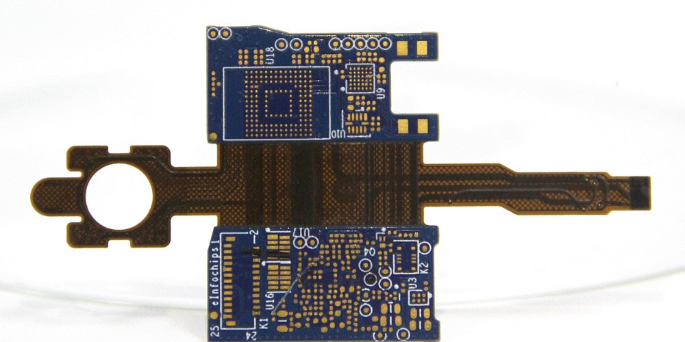
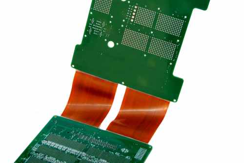
Rigid flex boards consist of multiple layers of substrate materials bonded together to form the combined rigid and flex structure. Here are the main components:
Rigid Substrate
The rigid sections of the PCB typically use higher thickness FR-4 material. This provides mechanical stability while maintaining affordability. Common thicknesses range from 0.2mm to 1.6mm.
Flexible Substrate
The flex sections use polyimide film or polyester base materials. These provide flexibility and bendability. Common flexible substrate thicknesses range from 25μm to 100μm.
Adhesive Layers
Bonding films are used to attach the rigid and flex layers together. Thermosetting adhesives permanently bond the layers under heat and pressure. Common adhesive films include acrylic, phenolic butyral, and epoxy.
Reinforcement Material
Some rigid flex boards contain extra reinforcement material in the flex area. This adds mechanical stability to prevent flex cracks. Common reinforcements are polyimide film and mesh glass fabric.
Coverlay
Coverlay is a protective coating applied to the flex circuitry to prevent abrasion and environmental damage. Polyimide films are commonly used as coverlay.
Stiffeners
Selective areas sometimes use rigid stiffeners embedded in the flex layer. These provide localized reinforcement for components or connectors.
Rigid Flex Board Design Considerations and Guidelines
Proper design is critical for manufacturing functional and reliable rigid flex boards. Here are some key guidelines for rigid flex design:
Layer Stackup
- Plan layer stackup with adequate dielectric separation between conductors
- Use thicker dielectrics for high voltage applications
- Minimize number of layers where possible
Trace Routing
- Use wider trace widths and spacing in flex sections
- Avoid 90 degree bends in conductors – use rounded curves instead
- Route critical signals first before filling in other traces
Component Placement
- Place most components in rigid sections of the PCB
- Avoid placing parts in areas that will flex – instead route to rigid sections
- Watch component clearances in flexing areas
Board Stiffness
- Use thicker rigid sections for maximum stiffness
- Incorporate stiffeners and pads for increased stability
- Allow room for normal flexing movement
Flex Cuts
- Design precise cut lines between rigid and flex sections
- Avoid sharp corners – use rounded edges instead
- Account for slit tolerances in layout
Flex Bends
- Bend areas should be as large as possible
- Maintain minimum bend radius specified by flex substrate manufacturer
- Include teardrop shapes at transitions between bent and straight sections
Following these guidelines will help produce a rigid flex design optimized for manufacturability and reliability.
Rigid Flex Board Manufacturing Processes
Rigid flex PCBs require specialized fabrication compared to standard rigid boards. Here are some of the essential manufacturing processes:
Layer Bonding
- Rigid and flex layers are bonded using heat and adhesive films
- Automated heated presses laminate layers under precise temperature and pressure
- Bonded boards are cooled and inspected for defects
Etching
- Photolithography transfers conductor patterns onto each layer
- Etchants remove unwanted copper to form traces and pads
- Both chemical and plasma etching used
Via Formation
- Mechanical drilling forms vias and through-holes
- Laser drilling offers higher density microvias
- Plated copper makes connections between layers
Solder Mask
- LIquid photoimageable solder mask (LPI) applied and imaged
- Areas for soldering exposed, while conductors are protected
Flex Cuts
- Automated routing machines cut lines between rigid and flex sections
- Precise machining required to avoid tearing flexible layers
Testing and Inspection
- Electrical testing checks continuity and isolates defects
- Automated optical inspection (AOI) verifies clearances and features
- X-ray inspection detects hidden layer flaws
Rigid flex manufacturing requires advanced processes, precision tools, and tight tolerances to produce high-quality PCBs.
Cost Factors for Rigid Flex Boards
Several factors affect the costs of rigid flex PCBs:
Layer Count
More layers adds processing complexity and requires additional materials. High layer counts increase costs.
Board Size
Larger boards use more base materials. Maximum panel sizes affect cost efficiency.
Feature Density
Denser designs require finer lines, smaller vias, tighter tolerances. This drives up cost.
Flexibility
Highly flexible boards need additional constraint layers and handling. This adds cost.
Volume
Higher order volumes benefit from economies of scale. Per unit cost drops with volume.
Testing
Extensive electrical testing and inspection adds cost. Complex boards require more testing.
Lead Time
Normal lead times range from 2-8 weeks. Rush orders can incur premium fees.
In general, work with your PCB manufacturer early in the design process to estimate costs based on your specific requirements.
Rigid Flex Boards vs. Flexible Circuits
While related, rigid flex boards differ from pure flexible PCBs:
Rigid Flex Board
- Combination of rigid and flexible substrates
- Rigid areas for strength and component mounting
- Flex areas for adaptable connections
- Can have conductors on both sides
- More complex processing
Flexible Circuit
- Usually only flexible substrate throughout
- No rigid sections
- Good for dynamic flexing and motion
- Typically single-sided conductors
- Simpler design and fabrication
Rigid flex boards offer unique advantages of both technologies. But pure flex circuits tend to be lower cost for solely flexible applications.
Frequently Asked Questions
What are some good applications for rigid flex boards?
Good applications for rigid flex include wearable devices, cameras, consumer electronics, automotive electronics, and medical devices. The combination of rigid and flex makes them well suited for many complex layouts.
What design software should be used for rigid flex boards?
Specialized PCB layout tools like Cadence Allegro and Mentor Xpedition offer advanced rigid flex design features. These tools precisely model bends and validate electrical and mechanical integrity.
How many times can a rigid flex board be flexed before failing?
Lifetime flex performance depends on the materials used. Well-designed boards can withstand hundreds of dynamic flex cycles. With proper strain relief and component placement, rigid flex boards can achieve long flex life.
Can components be mounted on the flex sections of a rigid flex board?
It is generally advised to avoid placing components on dynamic flex areas. Only very small, lightweight components should be considered. Rigid sections are best for component placement.
How small can trace widths and spaces be on rigid flex boards?
Traces and spaces down to around 4/4 mils (0.1mm) are typical for rigid sections. Flex sections usually require coarser 6/6 spacing for reliability. Finer geometries are possible but increase cost.
Conclusion
Rigid flex PCBs provide an invaluable technology for advanced electronics with their ability to integrate rigid and flex materials together into one board. Whether you are designing a sleek wearable product or advanced medical device, understanding rigid flex materials, design techniques, manufacturability, and costs provides critical knowledge to harness their unique capabilities. With the guidelines and information covered in this article, you are now well prepared to effectively utilize rigid flex technology in your next product design.