


Rigid flex assemblies (RFAs) integrate rigid printed circuit boards (PCBs) and flexible circuits into a single interconnect solution. They provide design flexibility to fit within confined spaces and enable 3D routing. As products become smaller and more complex, rigid flex is increasingly used in wearables, medical devices, aerospace, and consumer electronics. This article provides an overview of rigid flex technology, design considerations, assembly, and applications for PCB designers.
What is Rigid Flex?
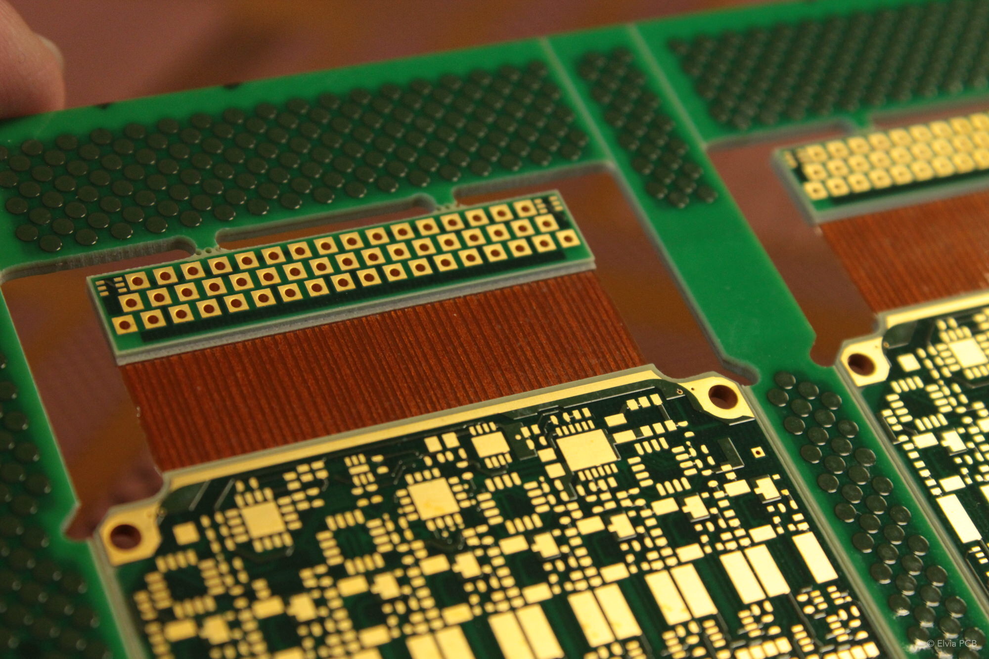
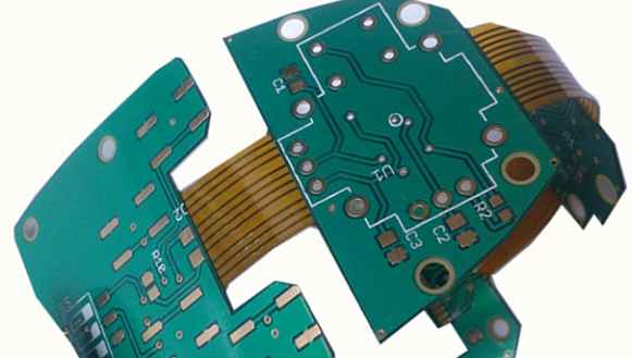
A rigid flex assembly combines rigid PCBs and flexible circuits laminated together into a single interconnect package. The rigid sections provide mechanical stability and support for surface mount components. The flexible sections enable out-of-plane interconnections between rigid sections.
Rigid flex assemblies typically consist of:
- Rigid FR4 PCB sections – Made of a glass reinforced epoxy laminate material. Provides structure and allows for high-density component mounting.
- Flexible polymer sections – Usually polyimide or polyester substrates clad with copper foil traces. Enables dynamic flexing and 3D routing capabilities.
- Coverlay/bondply layer – A thin laminate layer that bonds the separate rigid and flex layers together.
Benefits of Rigid Flex
Compared to standard rigid PCBs, rigid flex offers several advantages:
- Space savings – Flexible sections allow routing in 3 dimensions to optimize space in compact products.
- Reduced connectors – Eliminates interconnects between separate rigid boards since they are integrated into one assembly.
- Enhanced reliability – Integrated single assembly avoids interconnect failures between multiple PCBs.
- Design flexibility – Bend radius enables wrapping flex circuits around edges and folding into complex geometries.
- Simplified assembly – Combined into one part for faster production and lower cost.
Rigid Flex Construction
Rigid flex assemblies can be fabricated in different configurations:
Single Sided Flex
A rigid board connected to a flex layer on one side only. Simplest and least expensive rigid flex design.
Double Sided Flex
Rigid layers sandwich a flex layer in between. Enables routing on both sides of the flex.
Multi-Layer Rigid Flex
Multiple alternating layers of rigid and flex materials. Allows for complex routing and component density but is more challenging to manufacture.
Folding Rigid Flex
Flexible sections are designed to allow folding and compact 3D configurations. Requires special care to avoid exceeding bend radius limits.
Design Considerations
Designing a successful rigid flex assembly requires close collaboration between the mechanical engineer and PCB designer to balance the interconnect requirements with the physical and mechanical constraints. Here are some of the main design considerations:
Layer Stackup
- Determine number of conductive layers needed – more layers allow higher routing densities.
- Stackup thickness impacts flexibility – thicker constructions are less bendable.
- Match coefficients of thermal expansion (CTE) to avoid stresses during flexing.
- Ensure adequate bonding between separate layers.
Bend Radii
- Minimum bend radius determined by flex material properties.
- Typical minimum is 0.010 in (0.254 mm) but can vary.
- Tighter bends increase risk of flex damage and cracked traces.
- Strain relief patterns on traces enable tighter bend radii.
Component Placement
- Limit components in flexible areas to maintain bendability.
- Avoid placing heavy components near folds to reduce stress.
- Use adhesives to reinforce component attachments in flex areas.
Routing Strategies
- Route critical signals on inner layers for protection.
- Use vias to transition traces between rigid and flex layers.
- Stagger or angle traces at bend areas to allow flexing.
- Mind trace widths and spacing at bends due to elongation and compression.
Board Outline
- Fold areas dictate the rigid-flex junction outlines.
- Avoid sharp corners where traces transition between rigid and flex.
- Non-rectangular board outlines possible but require special manufacturing steps.
Shielding and Grounding
- High-speed designs need adequate signal isolation and containment.
- Ensure ground continuity between rigid and flex sections.
- Careful component placement avoids coupling and emissions issues.
Thermal Management
- Heavier copper planes helps distribute heat in rigid sections.
- Limit power dissipation in the thinner flexible regions.
- Thermal vias, openings, edge plating help remove heat.
- Use lower Tg polymer flex materials to withstand higher temps.
Manufacturing Rigid Flex
Producing reliable rigid flex assemblies requires advanced fabrication techniques and specialized materials. Here is an overview of the rigid flex manufacturing process:
Layer Lamination
- Alternating layers of rigid and flex materials are precisely aligned and bonded together under heat and pressure.
- Bonding films join the material layers into an integrated structure.
- Registration accuracy is critical to avoid opens or shorts between layers.
Imaging and Etching
- Photolithography transfers the copper patterns onto each layer.
- Etching removes unwanted copper to form the designed traces and pads.
- Tight process controls maintain trace resolution and tolerance.
Coverlay Application
- A thin laminate layer bonds the rigid and flex layers together.
- Coverlay provides electrical isolation and environmental sealing.
- Cutouts in coverlay allow soldering to pads on the flex layer.
Solder Mask and Finishing
- Solder mask coats the assembly for corrosion protection.
- Areas requiring solder bonding are left exposed.
- Hot air solder leveling (HASL) applies solder coating to exposed pads.
Singulation
- Rigid sections are routed apart into individual boards.
- Tabs hold boards in place during assembly.
- Special fixtures support the thin flexible regions during routing.
Testing and Inspection
- Electrical testing checks for shorts, opens, and continuity.
- Automated optical inspection looks for defects and flaws.
- Samples tested for number of flex cycles to qualify reliability.
Rigid Flex Assembly Design Rules
Rigid flex manufacturing imposes constraints that impact the PCB layout. Following design rules specific to rigid flex materials, stackup, and construction ensures the assemblies can be fabricated and survive flexing stresses:
| Design Aspect | Rule Examples |
|---|---|
| Minimum Bend Radii | 0.010 in (0.254 mm) radius typical for flex sections |
| Trace Routing | Avoid 90 deg bends, use teardrops at junctions |
| Annular Rings | 4 mil annular ring minimum at pads |
| Solder Mask Pullback | 3 mil clearance from pads |
| Plated Through Holes | 1:1 ratio of hole size to board thickness |
| Component Spacing | 0.010 in spacing minimum in flex areas |
| Copper Weight | 1/2 oz (18 um) copper typical for flex layers |
Consult your rigid flex vendor’s specific capabilities and limitations when laying out the design.
Applications of Rigid Flex Assemblies
The unique benefits of rigid flex technology make it well suited for products that require:
- Tight space constraints – Enables compact 3D arrangements and routing between multiple rigid sections. Useful in portable and handheld products.
- Dynamic flexing – Folding flex circuits accommodate movement and adjustments. Used in adjustable arm mechanisms and robotics.
- Conformal mounting – Can integrate and conform to curvy or irregular mounting surfaces. Used in wearable devices and implants.
- High density – Thin, tightly spaced traces placing components on both sides of a flex layer. Found in ultra-compact medical instruments.
- Reliability – Vibration resistance and elimination of separate interconnections improves reliability in aerospace and defense systems.
Here are some examples of products using rigid flex assemblies:
- Wearable devices – Smart watches, fitness bands
- Laptop and tablet computers
- Mobile phones
- Digital cameras
- Medical instruments – Endoscopes, implants
- Industrial robotics
- Missile guidance systems
- UAVs, spacecraft
Rigid Flex Design Resources
- PCB design tools – Constraint managers aid rigid flex layout and checking of rules.
- CAD libraries – Component footprints qualified for rigid flex assemblies.
- Fabrication specifications – Material datasheets detail properties and processing requirements.
- IPC standards – IPC-2223C provides rigid flex design and assembly requirements.
- Testing procedures – Qualification and reliability testing methods specific to rigid flex.
- Vendor expertise – Rigid flex suppliers provide design assistance and training.
Frequently Asked Questions
Here are some common questions about rigid flex design and manufacturing:
What types of materials are used in rigid flex construction?
The rigid sections use standard FR-4 or high performance thermoset laminates. Flexible sections are typically polyimide or polyester films. Adhesive bondplys join the layers.
What are some ways to allow traces to flex reliably?
Use teardrop junctions, staggered traces, and strain relief patterns like sine waves or zig-zags. Avoid 90 degree angles.
How many flex cycles can rigid flex assemblies withstand?
Properly designed assemblies can achieve several thousand flex cycles. Materials, bend radius, and routing strategies determine flex life.
What are some methods for attaching components to flexible circuits?
Adhesives, solder joints, thermocompression bonds, and snap-on component clips. Avoid rigid attachments near bend areas.
How are component packages with leads attached?
Through hole component leads require plated through holes. Careful attention to hole fill requirements avoids fracturing during flexing.
Can rigid flex circuits enable flexible printed electronics applications?
Yes, techniques like inkjet printing conductive traces enable integrating printed electronics onto flexible circuits.
Conclusion
Rigid flex represents an advanced PCB technology that enables innovative mechanical and electrical design approaches. As products continue getting smaller and more complex, rigid flex allows for greater packaging efficiency, reliability, and capability. By collaborating across disciplines and applying specialized design practices, electrical engineers and PCB layout designers can effectively harness the benefits of rigid flex assemblies.