

Introduction
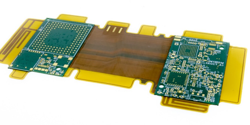
Rigid Flex Printed Circuit Boards (PCBs) are increasingly being adopted for use in military and defense applications that demand reliability, durability and high performance in extreme environments. Rigid Flex PCBs provide the ability to integrate rigid and flexible materials onto a single circuit board, allowing for greater flexibility in product design, more efficient use of space, and improved reliability compared to conventional rigid PCBs.
In military settings, Rigid Flex PCBs enable the creation of electronics that can withstand shock, vibration, moisture, dust and rapid temperature changes. Components can be carefully placed on the rigid portions while interconnects are routed through the flexible layers. This article will provide an overview of design and manufacturing considerations for developing Rigid Flex PCBs for military and high-reliability applications.
Rigid Flex PCB Design Guidelines
Careful design is critical for ensuring Rigid Flex PCBs meet the performance, reliability and durability requirements of military applications. Here are some key guidelines:
Layer Stackup
- Determine number of conductive layers needed for trace routing. More layers provide greater flexibility but add cost.
- Choose dielectric materials that balance flexibility with rigidity. Common materials: polyimide, polyethylene terephthalate (PET), polyethylene naphthalate (PEN).
- Stackup arrangement impacts flexibility. Placing outer layers farther apart increases bend radius.
Flex-to-Rigid Transition
- Minimize number of flex-to-rigid transitions. Stress concentration can lead to cracks and failures.
- Optimize placement and distribute transitions evenly. Avoid sharp angles.
- Use adhesives or coversheets to reinforce transitions.
Component Placement
- Position components in rigid sections for stability and heat dissipation.
- Ensure sufficient clearance around components for dynamic flexing.
- Strategically place components to balance board stiffness.
Trace Routing
- Use 45° or curved traces in flex areas instead of 90° turns.
- Avoid traces perpendicular to bend axis. Places stresses on solder joints.
- Wider traces better withstand dynamic flexing. Minimum 8-10 mil trace/space.
Vias and Pads
- Use large annular rings around pads and vias for reliability.
- Place vias in rigid sections only. Avoid in flexing areas.
- Adhesives and filled vias can relieve stress in via barrels.
Stiffening and Reinforcement
- Increase board thickness in high stress areas.
- Strategically place stiffeners, ribs and inserts to direct flexing motion.
- Clamping mounts can constrain dynamic movement during use.
Military-Grade Rigid Flex PCB Materials
Choosing the right PCB materials is crucial for military performance requirements. Here are key considerations:
Dielectric Layers
- Polyimide (Kapton) – Temp range -269 to 400°C. High strength and durability.
- PEN – Temperature resistant to 180°C. Tear resistant. Low moisture absorption.
- PET – Economical alternative to polyimide. Temperature range -40 to 150°C.
- PTFE composites – Withstands 260°C. Low dielectric loss.
Copper Foil
- 1/2 to 2 oz thickness typically used. Thicker copper better withstands vibration.
- Rolled annealed copper preferred for fatigue resistance vs electro-deposited.
- Have low porosity for reduced oxidation and galvanic corrosion.
- Expand copper foil strain window to improve flex life.
Cover Films and Coatings
- Liquid photoimageable coverlay adds flex reinforcement.
- Solder mask over bare copper (SMOBC) protects traces.
- Conformal coatings resist moisture, dust, chemicals.
Board Finishes
- Immersion silver – Ideal for harsh environments. Least prone to dendrite growth. High durability and thermal resistance. May require sealing.
- Immersion tin – Solderable finish with excellent anti-whisker properties. Well-suited to flex boards.
- ENIG – Gold provides corrosion resistance while nickel is a diffusion barrier. More costly.
- HASL – Lead-free solder finish usable but less ideal for high-reliability flex boards.
Rigid Flex PCB Manufacturing Processes
Producing reliable military-grade Rigid Flex PCBs requires robust manufacturing and quality control:
Layer Lamination
- Layers precisely aligned and bonded under high heat and pressure.
- Adhesive sheets alternate with dielectric layers. Flows during lamination.
- Excess adhesive flow trimmed to maximize flexibility.
Hole Formation
- Dry film photoresist applied. Exposed and developed.
- Holes drilled through rigid sections only. Avoid in flex areas.
- Plated through holes (PTHs) then electrically connect layers.
Copper Patterning
- Photoresist and imaging used to pattern copper features and traces.
- Etching removes copper not protected by photoresist.
Solder Mask Application
- Liquid photoimageable (LPI) solder mask preferred for durability, resistance.
- Full tenting of solder mask over flex areas for insulation.
Final Finishes and Coatings
- Electrolytic nickel/gold (ENIG), immersion silver (ImAg) and immersion tin (ImSn) finishes.
- Conformal coatings provide environmental and moisture protection.
Test and Inspection
- Electrical testing ensures continuity, isolation and function.
- Automated optical inspection looks for defects and flaws.
- QC throughout the process for quality assurance.
- Imaging such as x-ray looks for potential latent defects.
With proper design and manufacturing, Rigid Flex PCBs can provide reliable performance in the demanding conditions encountered in aerospace, military and other high-reliability applications. Let’s look at some frequently asked questions.
FAQs About Military Rigid Flex PCBs
What are some typical applications for Rigid Flex PCBs in defense systems?
Common applications include missiles and munitions guidance systems, radars, soldier-worn systems, communications, displays, targeting systems, drones/UAVs and aerospace systems. Rigid Flex allows dense, complex circuitry that can withstand intense vibration, shock, acceleration and temperature changes.
How are Rigid Flex PCBs tested and qualified for military and aerospace use?
Rigid Flex PCBs undergo rigorous testing such as vibration, mechanical shock, acceleration, salt fog, temperature cycling and other relevant MIL-SPEC environmental testing. Materials and construction methods must pass DPA, IST and other inspections. Workmanship standards are higher than commercial grade PCBs.
What design factors are important for dynamic flexing endurance?
Trace widths wider than 8-10 mils, avoiding 90° traces, minimal rigid-to-flex transitions, wide pad/via annular rings, strategic placement of components and stiffeners, using rolled annealed copper, and robust bonding of layers all improve flexing endurance.
How do costs compare between Rigid Flex PCBs and rigid boards?
The specialized materials and processes involved generally make Rigid Flex PCBs more expensive than rigid only boards. However, they enable reduced system size/weight, part consolidation, and improved reliability that justify the added cost in mission-critical defense applications.
How large of Rigid Flex PCBs can be manufactured?
Technology can accommodate very large boards – 18+ inches long, 8 inches wide. However, for optimal manufacturing yield and reliability, smaller rigid-flex sections combined into larger assemblies may be preferred. Rigid sections above 4-8 inches long should often be separated by flexible portions.
Conclusion
With their inherent durability, miniaturization and performance advantages, PCBs with both rigid and flexible components will continue gaining adoption in demanding defense and aerospace applications. Following robust design and manufacturing principles is key to producing Rigid Flex PCBs that can survive and function reliably in the harsh, extreme environments often encountered in military settings. With rigorous testing, qualification and component level as well as system level reliability engineering, Rigid Flex PCB technology enables mission critical electronics to meet their stringent requirements.