


Introduction to M4 Mounting holes
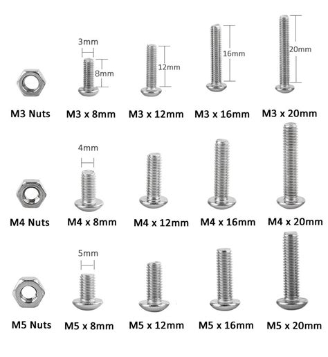
M4 mounting holes are a common feature in various applications, from industrial machinery to consumer electronics. These holes are designed to accommodate M4 screws, which have a nominal diameter of 4 mm. Understanding the dimensions and specifications of M4 mounting holes is essential for engineers, designers, and technicians working on projects that require secure fastening.
In this comprehensive article, we will dive deep into the world of M4 mounting hole dimensions, covering everything from basic terminology to advanced design considerations. Whether you are a seasoned professional or a beginner learning about fasteners, this guide will provide you with the knowledge and insights needed to work effectively with M4 mounting holes.
Basic Terminology and Definitions
Before we delve into the specifics of M4 mounting hole dimensions, let’s familiarize ourselves with some basic terminology and definitions:
- Nominal Diameter: The nominal diameter of a screw refers to its size designation, which is based on the outer diameter of the screw threads. In the case of M4 screws, the nominal diameter is 4 mm.
- Pitch: The pitch of a screw is the distance between two adjacent threads, measured along the screw’s axis. M4 screws typically have a standard pitch of 0.7 mm, although fine pitch variations (0.5 mm) are also available for specific applications.
- Thread Profile: The thread profile describes the shape of the screw threads. M4 screws follow the metric thread profile, which is characterized by a 60° angle between the threads and a flat crest and root.
- Clearance Hole: A clearance hole is a hole that allows a screw to pass through freely without engaging the threads. The diameter of a clearance hole is slightly larger than the screw’s nominal diameter to provide adequate clearance.
- Tapped Hole: A tapped hole, also known as a threaded hole, is a hole with internal threads that mate with the screw’s external threads. The diameter of a tapped hole is slightly smaller than the screw’s nominal diameter to ensure proper thread engagement.

M4 Screw Dimensions
To understand M4 mounting hole dimensions, it is essential to have a clear understanding of the dimensions of M4 screws. The following table summarizes the key dimensions of standard M4 screws:
| Nominal Diameter | Pitch | Major Diameter | Minor Diameter | Head Diameter (Pan) | Head Height (Pan) |
|---|---|---|---|---|---|
| 4 mm | 0.7 mm | 4.0 mm | 3.242 mm | 7.0 mm | 2.6 mm |
Note that the head dimensions provided in the table correspond to the most common pan head style. Other head styles, such as countersunk or button heads, may have different dimensions.

M4 Clearance Hole Dimensions
When designing a clearance hole for an M4 screw, it is important to provide sufficient clearance to allow the screw to pass through without interference. The recommended diameter for an M4 clearance hole is 4.5 mm, which provides a clearance of 0.25 mm on each side of the screw.
It is worth noting that the clearance hole diameter may vary depending on the specific application and the tolerances of the components involved. In some cases, a slightly larger clearance hole (e.g., 4.6 mm or 4.8 mm) may be necessary to accommodate Manufacturing
tolerances or to allow for easier assembly.

M4 Tapped Hole Dimensions
When creating a tapped hole for an M4 screw, the hole diameter should be slightly smaller than the screw’s nominal diameter to ensure proper thread engagement. The recommended tap drill size for a standard M4 tapped hole is 3.3 mm.
The depth of the tapped hole depends on the length of thread engagement required for the specific application. As a general rule, the minimum thread engagement for a secure connection should be at least 1.5 times the screw’s nominal diameter. For an M4 screw, this means a minimum thread engagement of 6 mm.
The following table provides the recommended tap drill sizes and tapping depths for M4 tapped holes:
| Nominal Diameter | Tap Drill Size | Tapping Depth (Minimum) |
|---|---|---|
| 4 mm | 3.3 mm | 6 mm |
Design Considerations for M4 Mounting Holes
When designing components with M4 mounting holes, there are several key factors to consider to ensure a secure and reliable connection:
Material Thickness
The thickness of the material being fastened plays a crucial role in determining the appropriate mounting hole dimensions. For M4 screws, the recommended minimum material thickness is 2 times the screw’s nominal diameter, which equates to 8 mm.
If the material thickness is less than 8 mm, it may be necessary to use a threaded insert or a backing nut to provide additional thread engagement and prevent the screw from stripping the threads.
Edge Distance and Spacing
To prevent the material from cracking or splitting, it is important to maintain sufficient edge distance and spacing between mounting holes. The recommended minimum edge distance for M4 mounting holes is 2 times the screw’s nominal diameter (8 mm), while the minimum spacing between holes should be 3 times the nominal diameter (12 mm).
In cases where space is limited, or the material is particularly strong, these distances can be reduced. However, it is essential to conduct appropriate stress analysis and testing to ensure the integrity of the connection.
Countersinking and Counterboring
In some applications, it may be desirable to have the screw head sit flush with or below the surface of the material. This can be achieved through countersinking or counterboring.
Countersinking involves creating a conical recess around the mounting hole to accommodate the angled underside of a countersunk screw head. The depth and diameter of the countersink depend on the specific screw being used.
Counterboring, on the other hand, involves creating a cylindrical recess around the mounting hole to accommodate the entire screw head. The depth and diameter of the counterbore should match the dimensions of the screw head.
When designing countersunk or counterbored holes, it is important to ensure that the remaining material thickness is sufficient to withstand the anticipated loads.
Frequently Asked Questions (FAQ)
- What is the difference between a clearance hole and a tapped hole?
A clearance hole is a hole that allows a screw to pass through freely without engaging the threads, while a tapped hole has internal threads that mate with the screw’s external threads. - Can I use a larger clearance hole diameter than the recommended 4.5 mm for M4 screws?
Yes, in some cases, a slightly larger clearance hole (e.g., 4.6 mm or 4.8 mm) may be necessary to accommodate manufacturing tolerances or to allow for easier assembly. However, it is important not to make the clearance hole too large, as this can reduce the strength of the connection. - What is the minimum thread engagement for an M4 screw?
The minimum thread engagement for a secure connection should be at least 1.5 times the screw’s nominal diameter. For an M4 screw, this means a minimum thread engagement of 6 mm. - Can I use a smaller edge distance or spacing between M4 mounting holes than the recommended values?
In cases where space is limited, or the material is particularly strong, the edge distance and spacing can be reduced. However, it is essential to conduct appropriate stress analysis and testing to ensure the integrity of the connection. - What should I do if the material thickness is less than the recommended 8 mm for M4 screws?
If the material thickness is less than 8 mm, it may be necessary to use a threaded insert or a backing nut to provide additional thread engagement and prevent the screw from stripping the threads.
Conclusion
M4 mounting holes are a critical aspect of many engineering and design projects, and understanding their dimensions and specifications is essential for creating secure and reliable connections. By following the guidelines outlined in this article, you can ensure that your M4 mounting holes are designed and implemented correctly, whether you are working on industrial machinery, consumer electronics, or any other application.
Remember to consider factors such as material thickness, edge distance, and spacing when designing M4 mounting holes, and always conduct appropriate testing and analysis to verify the strength and integrity of the connection.
With this comprehensive guide, you now have the knowledge and tools needed to work effectively with M4 mounting hole dimensions. Apply this information to your projects, and you will be well on your way to creating robust and reliable fastening solutions.