


Introduction to Flex Circuits
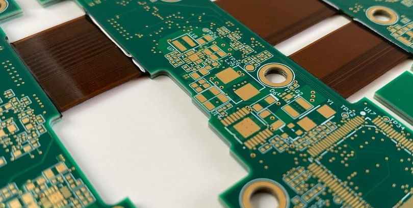
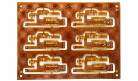
A flexible printed circuit (FPC), also known as a flex circuit, is a type of printed circuit board (PCB) that is made of flexible dielectric materials such as polyimide or polyester. Unlike traditional rigid PCBs, flex circuits can bend and flex to fit mechanical constraints within electronic devices. They are commonly used in products where flexibility, space savings, or dynamic flexing is required such as portable electronics, medical devices and automotive applications.
Flex circuits provide several key advantages:
- Can conform to 3D shapes and dynamic flexing
- Lightweight and take up less space
- Allow for greater component density
- Enable movement within electronic devices
- Withstand vibration and impact
- Lower assembly costs compared to wire harnesses
Some key terms used with flex circuits include:
- Dielectric layers: The flexible insulating material that forms the base of the flex circuit, usually polyimide or polyester films.
- Conductors: The copper traces etched onto the dielectric that carry signals and power.
- Coverlay/Covercoating: A thin dielectric layer laminated over the conductors for protection.
- Stiffeners: Thicker polyimide or metal strips added for support in rigid sections.
Flex Circuit Design Considerations
Designing a functional flex circuit requires considerations for the intended application requirements, manufacturing capabilities and assembly processes. Here are some of the main design factors for flex circuits:
Layer Stackup
The cross-sectional layer structure of a flex circuit includes alternating layers of dielectric and copper conductors, often with coverlays or stiffeners added. Simple single layer designs to complex multilayer stackups are possible. The number of layers, conductor density, dielectric films and thickness are specified based on circuit complexity and manufacturing capabilities.
Conductor Layout
The width and spacing of copper traces are designed to meet current capacity and impedance requirements. Common trace widths range from 0.1mm to 0.3mm. Narrower traces can be used but may require thicker copper. The yield strength of the dielectric material also impacts minimum trace spacing.
Bend Radius
A primary advantage of flex circuits is the ability to bend dynamically. The minimum bend radius is an important parameter and depends on the stackup. Tighter bends increase stresses and can crack rigid sections or traces. Recommended bend radius is typically 3-10x the total flex thickness.
Stiffener Locations
Discrete stiffeners made of thicker polyimide or metal strips are often added to provide rigidity and support for components or connectors. Stiffener locations are specified during design layout.
Component Placement
Planning the layout of components on flex circuits is critical, considering the dynamic bending. Rigid components should be oriented perpendicular to the bend axis and placed appropriately to avoid overstressing solder joints.
Vias
Vias or interconnects between layers are used to route signals between layers. Laser drilled microvias with conductive plating allow connections between fine pitch traces. Filled vias provide reliability under dynamic flexing.
Test Points
Due to the limited space, testpoint access needs to be considered during the layout. Testpoints allow for in-circuit testing during assembly or troubleshooting faults.
Flex Circuit Fabrication Process
Flex circuits boards utilize many similar PCB fabrication processes but also specialized techniques tailored for flexible materials. The manufacturing process typically involves:
Imaging/Lithography
A photoresist layer is laminated onto the base dielectric film. The circuit layout artwork is then exposed onto the photoresist using lithographic imaging to create a patterned mask.
Etching
The unwanted copper is etched away, leaving only the desired conductor traces under the photoresist mask. Common etching processes include chemical etching or plasma etching.
Stripping and Cleaning
The remaining photoresist is then stripped off and the flex boards are cleaned in preparation for the next steps.
Dielectric Lamination
Additional layers of adhesive dielectric films, like polyimide, are laminated together to build up multi-layer stackups. Drilled holes are made conductive by plating.
Conductor Plating
Electrolytic copper plating is used to plate conductive traces onto the dielectric layers and plate through drilled holes to form plated through holes (PTHs) for vertical interconnections between layers.
Etch Resist
A photoimageable coverlay material is laminated over the conductors and imaged to form a protective resist mask over the traces during covercoat etching.
Covercoat Etch
The exposed coverlay is etched away to selectively leave only the desired insulating coverlay material over the protected copper traces.
Component Assembly
Components and connectors are populated onto the flex boards through soldering, conductive adhesives or mechanical attachments.
Final Testing
Each board undergoes electrical testing. Automated optical inspection (AOI) and other measurements ensure quality and reliability.
Flex Circuit Applications
Flexible printed circuits are found in a wide range of products due to their advantages. Here are some common applications:
Consumer Electronics
Flex circuits are extensively used in mobile phones, tablets, laptops and other portable consumer electronics where lightweight and high component density PCBs are required. Flex allows complex interconnections in limited space.
Automotive
In vehicles, flex circuits wire many different control modules and systems such as airbag controls, engine controls, ABS braking systems, and sensors. Flex circuits withstand vibration while reducing weight versus cabling.
Medical Devices
In medical equipment like patient monitors, MRI scanners, and surgial tools, flex circuits provide interconnects that meet ergonomic and sterility needs. They can also enable disposable sensors and reduced cables.
Industrial
Flex circuits are increasingly adopted in manufacturing equipment to interconnect moving parts. They withstand repeated motion more reliably than wires. Use cases include robot arms, 3D printers, machine tools.
Wearables
For smartwatches, fitness bands, and head-mounted displays, flex PCBs conform to curvy enclosures and human bodies. They interconnect miniaturized electronics in ergonomic form factors.
Military/Aerospace
Rugged flex circuits meet demanding reliability needs in harsh environments like satellites, aviation systems, missiles and radar systems. Less maintenance versus cabling. Withstand vibration, corrosion, shock.
Internet of Things
Many IoT and wireless sensors utilize flex PCB antennas and interconnects. Flex allows integration in small enclosures and flexible “stick on” sensors on surfaces.
Trends and Innovations
As flexible circuits gain greater adoption, ongoing R&D is focused on pushing the boundaries of flex PCB technology:
- Extreme miniaturization – Denser circuits, thinner dielectrics, finer lines and spaces enable compact interconnects.
- Advanced multilayer flex – 12+ layer high density flex circuits in development, allowing highly complex rigid-flex combo boards.
- Stretchable circuits – Novel elastic conductors and dielectrics create circuits that can stretch and flex repeatedly. Enables wearable electronics.
- Embedded passives – Passive components like resistors and capacitors fabricated within the flex circuit layers. Saves space.
- 3D formed interconnect – Flexible circuits folded, twisted or formed into 3D shapes for unconventional form factors.
- Additive processes – Additive fabrication techniques like inkjet printing and aerosol jet printing allow direct printing of conductors and dielectrics. Reduces waste and costs versus etching.
- Rigid-flex integration – Combining rigid and flex materials for integrated combo boards with rigid sites for ICs/connectors and dynamic flexing interconnects.
Flex Circuit Challenges
While offering advantages, flexible circuits also come with some particular design and manufacturing challenges:
- Dynamic flex durability – Repeated bending and twisting can induce conductor cracks and connection failures over time. Careful design of bend regions is needed.
- Limited real estate – Thin, light flex circuits offer less space for traces and vias, requiring high density interconnect design.
- Warpage control – Layer to layer registration and lamination processes must minimize warpage of thin circuits.
- Fine features – Narrow conductors and spaces require tight process controls and advanced photolithographic capabilities.
- Plating adhesion – Creating reliable copper to dielectric adhesion for good conductor adhesion, especially under dynamic flexing.
- Scalability – Transitioning from prototyping to higher volume manufacturing while maintaining quality and reliability.
Flex Supplier Selection Criteria
Choosing the right flexible circuit supplier is key to successfully bringing flex PCB designs to production. Here are some key selection criteria:
- Technical capabilities – Assess their design rules, layer counts, line widths, tolerances, minimum bend radius etc. to meet requirements.
- Manufacturing processes – Evaluate their specific production processes and quality certifications.
- Supply chain management – Verify their sourcing and availability of flex circuit materials to ensure stable lead times.
- Quality controls – Review their quality assurance procedures, testing methods, acceptable quality levels, and traceability.
- Qualifications and certifications – Relevant qualifications like ISO 9001 as well as ITAR or FDA registration for regulated industries.
- Prototyping services – Ability to build prototype and low volume designs can accelerate development before ramping to high volume production.
- Customer support – Check reviews and responses for post-sales technical support and design assistance.
- Cost competitiveness – Product pricing model and structure, geographic location, and scale of operations driving costs.
- Reliability and consistency – Examples of complex projects completed successfully with consistent quality over multiple runs.
Matching technical needs to manufacturing capabilities and quality expectations is essential to selecting the right flex circuit partner. Check multiple suppliers to find the best fit.
Conclusion
Flexible printed circuits enable innovative electronic designs in countless applications ranging from consumer tech to medical devices to aerospace systems. As electronic systems continue getting smaller and more complex, high reliability flex circuits provide lightweight, dynamic, and efficient interconnect solutions. With ongoing technology advancements, flex circuits have enormous growth potential to shape future electronics. Leveraging the specialized expertise of flex PCB suppliers is key to developing successful products with flexible circuits.
Frequently Asked Questions
What are some key differences between rigid PCBs and flex PCBs?
The main differences are:
- Materials – Flex PCBs use flexible base materials like polyimide instead of rigid FR-4.
- Thickness – Flex circuits are thinner, commonly 50-200 microns vs 1.6mm for rigid.
- Layers – Flex PCBs typically have 1-6 layers versus up to 30+ layers for rigid multilayer boards.
- Bend radius – Flex circuits can dynamically bend to small radii under 10mm. Rigid PCBs are not designed for flexing.
- Pitch and features – Flex PCB lines and spaces can be under 100 micron vs 150 micron for common rigid PCBs.
- Cost – On a per area basis, flex PCB fabrication initially costs more than rigid, but enables space savings in assembly.
What are some pros and cons of flex PCBs versus using cabling or wire harnesses?
Pros of flex circuits over cabling:
- Eliminates connectors and crimped terminations prone to failure
- Lower assembly cost and time
- Lighter weight – thinner conductors need less insulation
- Vibration and flexure resistance
- Takes up less space with shorter runs between connections
Cons of flex circuits:
- Limited temperature range – most flex materials max out at ~105-125C versus 150C+ for some wire insulations
- Can be more expensive for simple interconnects in low quantities
- Repair and modifications require complete replacement
How do costs of rigid-flex boards compare to full rigid boards?
Rigid-flex boards can cost 20-50% more than the equivalent interconnects implemented on rigid boards only. This is due to specialized materials, fabrication processes, and assembly considerations required for the flex portions. However, rigid-flex allows large space, weight, and wiring savings in end products through integration, so overall system costs can be lower. The tradeoff depends on specific design requirements.
Can conventional PCB assembly equipment be used for component assembly on flex circuits?
Most standard SMT assembly equipment is compatible with flexible circuits. However, flex boards require some special handing considerations such as:
- Maintaining minimum bend radius in conveyance systems
- Additional clamping or carrier bars to constrain flexing during assembly
- Adjustments for thinner flex boards in pick and place processes
- Modified soldering thermal profiles to account for lower flex circuit thickness
So while the same equipment can be used, some set up adjustments and process optimization is recommended when switching from rigid to flex assembly.
What kinds of testing and inspection are typically implemented for quality control of flex PCBs?
Typical quality control testing includes:
- Automated optical inspection (AOI) of conductor traces
- Dimensional metrology of conductors, spacings, and features
- Layer-to-layer registration measurements via microscopy
- Net connectivity/shorts testing
- Insulation resistance testing
- Cross sectional evaluation of plated holes and interconnects
- Adhesion pull testing of traces
- Solderability testing
- Destructive physical analysis (DPA) of solder joints, plating, etc.
- Flexural endurance testing of dynamic bending
Testing is implemented both on coupons to dial in processes and on finished boards, often with sampling rates defined by quality standards like IPC-6013.