
-
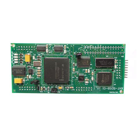
How does double sided SMT assembly work
What is Double-sided SMT Assembly? Double-sided Surface Mount Technology (SMT) assembly is a process where electronic components are mounted on both sides of a Printed Circuit Board (PCB). This technique allows for higher component density, improved performance, and reduced board size compared to single-sided SMT or through-hole assembly methods. Advantages of Double-Sided SMT Assembly Increased…
-
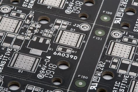
Soldermask requirements for high CTI boards
Understanding CTI and Its Significance Comparative Tracking Index (CTI) is a measure of a material’s ability to resist electrical tracking and erosion under high voltage stress and humid conditions. It is an essential parameter in PCB design, particularly for applications that require high electrical insulation and resistance to surface contamination. CTI is determined by subjecting…
-
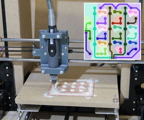
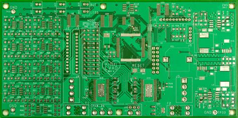
Pcb for wired printing head fabtotum
Introduction to PCB and Fabtotum A printed circuit board (PCB) is a crucial component in electronic devices that mechanically supports and electrically connects electronic components using conductive tracks, pads, and other features etched from one or more sheet layers of copper laminated onto and/or between sheet layers of a non-conductive substrate. PCBs can be single-sided,…
-
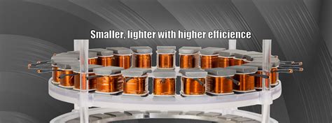
Axial Flux Permanent magnet BLDC Stator
Introduction to Axial Flux Motors Axial flux permanent magnet brushless DC (BLDC) motors have gained significant attention in recent years due to their unique design and performance advantages. Unlike conventional radial flux motors, axial flux motors have their magnetic flux running parallel to the motor’s shaft, resulting in a compact and efficient design. This article…
-
PCB Stackup Planning Simple
What is a PCB Stackup? A printed circuit board (PCB) stackup refers to the arrangement of copper and insulating layers that make up a PCB. It defines the number of layers, their order, and the materials used for each layer. Proper PCB stackup planning is crucial for ensuring the reliability, functionality, and manufacturability of the…
-
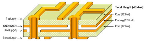
How to Design PCB Stackup
What is PCB Stackup? PCB stackup refers to the arrangement of layers in a printed circuit board (PCB). It is a critical aspect of PCB design as it determines the board’s electrical properties, mechanical strength, and manufacturability. A well-designed PCB stackup ensures proper signal integrity, minimizes electromagnetic interference (EMI), and reduces manufacturing costs. Key Components…
-
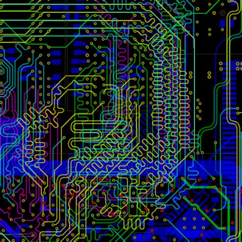
High speed PCB layout topology
Introduction to PCB topology Printed Circuit Board (PCB) topology plays a crucial role in the design and performance of high-speed electronic systems. As signal speeds continue to increase, the layout and routing of traces on a PCB become increasingly important to ensure signal integrity, minimize electromagnetic interference (EMI), and optimize overall system performance. In this…
-
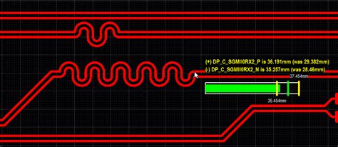
Differential trace impedance without reference plane
Understanding Differential Trace Impedance Differential trace impedance is a critical aspect of high-speed PCB design, particularly when dealing with differential signaling. In this article, we will delve into the concept of differential trace impedance and explore the challenges and solutions associated with maintaining consistent impedance in the absence of a reference plane. What is Differential…
Blog
Archive
Categorise
Recent Posts
- Common Mode Choke Selection: A Comprehensive Guide
- Common Fab and Assembly Design Errors To Avoid – AltiumLive 2024
- Commodore 128 Principal Engineer, Bil Herd on Best Practices for Learning a New CAD Tool
- Collecting All the Pieces You Need: What is a Bill of Materials?
- Collaborative Design Software: Create PCB Schematic Symbols for any Component