Introduction
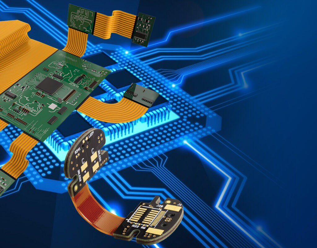
Flexible circuit boards, also known as flex circuits, are made of flexible insulating substrate materials that allow circuits to bend and flex without damage. Compared to traditional rigid printed circuit boards (PCBs), flex circuits can withstand repeated bending and twisting, making them ideal for use in dynamic applications where flexibility is required.
Some key applications of flexible circuit boards include consumer electronics, medical devices, industrial machinery, aerospace systems, and more. As emerging technologies drive demand for smaller and more dynamic electronic devices, the use of flex circuits is rapidly increasing. This article provides a comprehensive overview of the materials, properties, types, and applications of flexible circuit boards.
Flex Circuit Substrate Materials
The substrate, or base material, is what gives flex circuits their flexible properties. The most common flexible circuit substrates include:
Polyimide Films
Polyimide films like Kapton (DuPont) and Apical (Kaneka) are the most widely used flex circuit substrates. Polyimide offers:
- Excellent mechanical flexibility and bend radius
- High tensile strength and tear resistance
- Good chemical resistance and flame retardance
- Stable electrical properties over a wide temperature range
- Relatively low cost
Polyimide films are available in various thicknesses, with 1-3 mil being common for flex applications. Key properties can be enhanced by coating or laminating polyimide with adhesive or copper foil layers.
Polyester Films
Polyester films like Mylar (DuPont) and Melinex (Dupont Teijin) offer:
- Moderate flexibility
- Low cost
- Easy processing
However, polyester has lower mechanical strength than polyimide. It is commonly used for simple single-layer flex circuits without critical flexibility requirements.
Fluoropolymer Films
Fluoropolymer films like FEP (fluorinated ethylene propylene) and PTFE (polytetrafluoroethylene) offer:
- Excellent chemical resistance and dielectric properties
- Useful in high temperature applications up to 200°C
- Poor mechanical properties limit flexlife
Fluoropolymers are used in rigid-flex boards and in specific chemical-resistant applications.
Liquid Crystal Polymer (LCP) Films
LCP films like Zenite (Celanese) provide:
- Extremely high heat resistance
- Dimensional stability at elevated temps up to 280°C
- Relatively stiff with smaller bend radius than polyimide
- Excellent electrical and RF properties
- Higher cost than polyimide
LCP films are used in boards for autoclaving, military systems, and high-frequency analog circuits.
Others
Other flexible substrate materials used in specific applications include PEN (polyethylene naphthalate), polycarbonate, polyether ether ketone (PEEK), and composite materials. The choice depends on the required combination of flexibility, strength, temperature resistance, chemical resistance, dielectric properties, and cost.
Copper Foil Types
Flexible circuits use electrodeposited copper foil. Two main types are:
Rolled Annealed Copper
- Smooth surface
- Soft temper
- Lower cost
- Used for double-sided flex layers
Electrodeposited Copper
- Micro-roughened matte side promotes adhesion
- Stiffer temper for easier handling
- Used for multilayer flex innerlayers
- Costs more than rolled copper
Copper foils are available in standard 1⁄2, 1, and 2 oz thicknesses (per sq foot). Heavier copper up to 5 oz provides better conductivity for high-power circuits.
Flexible Circuit Types
Flexible circuits can be classified into three main types:
Single Layer Flex Circuits
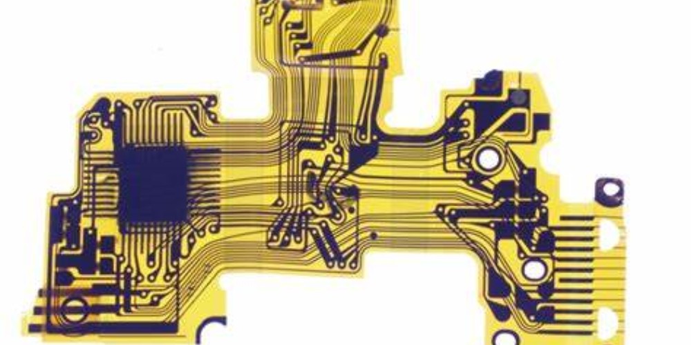
Consist of a single conductive copper layer on one side of the flexible substrate. Simple layouts with no plated through holes (PTHs). Low cost, widely used.
Double Layer Flex Circuits

Have conductive layers on both sides of the substrate. Allows more complex wiring patterns and PTH interconnections. Moderate cost increase over single layer.
Multilayer Flex Circuits
Have multiple conductive layers laminated together, allowing complex high-density interconnections. Cost increases with number of layers. Allows integration of components for flexible printed circuits.
Flexible Circuit Fabrication Process
Flexible circuits are fabricated using a subtractive process that starts with a laminate of the flexible substrate polyimide film and copper foils:
- Photoresist layers are laminated onto the copper surfaces
- The resist is exposed to light through custom artwork masks
- Development removes unexposed resist, leaving a pattern mask
- Etching chemically removes unmasked copper
- Resist is stripped off, leaving copper circuit traces
Multilayer boards require stacked laminates that are bonded together under heat and pressure before drilling and plating PTHs. Additional assembly processes can embed components and connectors.
Benefits of Flex Circuits
Compared to rigid circuit boards, key benefits of flexible circuits include:
- Dynamic flexing: Withstand repeated bending without cracking or damaging conductors
- Lightweight: Polyimide films are thinner than rigid FR-4 laminates
- Thin profile: Flex circuits can be fabricated thinner than 0.05 mm
- High reliability: Proven technology with established design and fabrication processes
- Simplified assemblies: Can eliminate wiring harnesses, connectors, and cables
- Design freedom: Can take any 2D or 3D form for optimal configuration
- Heat dissipation: Large thin surface area improves thermal dissipation
These benefits make flexible circuits ideal for many modern electronic products requiring miniaturization, movement, and reliability.
Applications of Flexible Circuit Boards
Major applications taking advantage of flexible circuit benefits include:
Consumer Electronics
Smartphones, tablets, wearables, appliances, etc. Flex circuits used in hinges, displays, cameras, sensors, antennas, etc. Allow compact folding and motion.
Automotive Electronics
Instrument panels, engine controls, infotainment displays. Withstand vibration while enabling integration.
Industrial
Process control boards, robotic arms, production line systems. Bendable interconnects suit moving parts.
Medical
Hearing aids, imaging systems, surgical tools. Enable compact, body-friendly devices.
Military/Aerospace
Avionics, guidance systems, radars, satellites. Rugged, heat-resistant, and reliable in extreme environments.
Research and prototyping
Flex circuits convenient for R&D testing of new form factors and rapid prototyping.
With growing demands for flexible, functional electronics, usage of flex circuits is increasing across practically every industry and application.
Design Considerations
While offering advantages, flexible circuits also involve unique design considerations:
- Flex life: Avoid low bend radii that can fatigue copper traces after repeated flexing.
- Dynamic folding: Account for reversing bend directions and flex fatigue.
- Stiffness: Dense circuits or thick copper can make flex boards too rigid.
- Thermal management: Polyimide’s low thermal conductivity requires careful thermal design.
- ESD protection: Polyimide prone to electrostatic discharge damage.
- Adhesion: Copper-polyimide adhesion can be challenging.
- Outgassing: Polyimide can release gas when heated, requiring venting.
- Economics: Determine when rigidflex boards offer better value than pure flex.
Experienced flex circuit designers understand these considerations to create reliable, optimized flexible PCB solutions.
Future Developments
Emerging trends for flexible circuits include:
- Fine lines and spaces: Fabrication below 25 micron circuit features.
- High layer counts: Continued growth in multilayer flex, driven by HDI technology.
- Embedded passives: Embedding capacitors, resistors, and other components.
- Stretchable circuits: Novel materials like liquid metals allow elastic stretching.
- Biocompatible materials: Flexible circuits interfacing with body tissues.
- Additive processing: Printed electronics and other additive methods to complement etching.
- Flexible hybrid electronics (FHE): Combining flex circuits with chip-scale packages.
- Internet of Things (IoT): Flexible sensor nodes and interconnects for smart systems.
As technology needs evolve, flexible circuit materials, design, and manufacturing will continue advancing.
Conclusion
Flexible circuit boards enable reliable electronic circuits that can bend, fold, twist, and flex without failure. Materials like polyimide films and additive copper allow dynamic mechanical movement. From wearable gadgets to mission-critical aerospace systems, flex circuits will continue improving electronic devices across industries. With sound design practices and expertise, engineers can leverage flexible PCB technology for all applications requiring size, weight, and reliability advantages over traditional rigid boards.
Frequently Asked Questions
What are some key differences between rigid PCBs and flex PCBs?
The main differences between rigid and flex PCBs are:
- Materials: Rigid PCBs use FR-4 glass reinforced epoxy. Flex PCBs use polyimide or other polymer films.
- Flexibility: Rigid PCBs cannot bend without damage. Flex PCBs are designed to withstand repeated dynamic bending.
- Layers: Rigid PCBs can have 30+ layers. Flex PCBs typically have 1-6 layers.
- Thermal conductivity: Rigid FR-4 is a better thermal conductor than flex materials.
- Density: Rigid PCBs can support higher density circuits and components.
- Cost: On a per area basis, flex PCB fabrication initially costs more than rigid.
- Applications: Rigid PCBs used where stiffness is required. Flex PCBs used where flexibility is required.
What are some considerations when selecting flexible circuit materials?
Key considerations when selecting flex circuit substrate materials include:
- Required flexibility (bend radius)
- Number of dynamic flex cycles needed
- Operating temperature range
- Thermal conductivity required
- Withstanding harsh chemical environments
- Dielectric properties such as breakdown voltage
- Mechanical properties such as tensile strength
- Cost and availability
The designer must balance electrical, mechanical, thermal, chemical, and cost needs when selecting optimal flex circuit materials for an application.
Can traditional leaded components be soldered onto flexible PCBs?
Yes, leaded through-hole and surface mount components can be soldered onto flexible circuit boards, with some considerations:
- Use adhesives to reinforce leads and prevent cracking joints
- Avoid placing heavy components in high-flex zones
- Use stress relief features on traces near joints
- Solder with minimal heat to avoid melting substrate
- Optimize board stiffness; too much flexibility adds stress
With proper design, traditional soldered components can be integrated onto flexible circuits.
What are some best practices for flex PCB layout?
Some layout tips for optimizing flexible PCBs include:
- Minimize trace lengths in flexing sections
- Avoid 90° bends of traces in flex areas
- Use curve shapes instead of sharp angles
- Provide gradual teardrop pads at junctions
- Keep high density wiring away from flex zones
- Duplicate grounds for better bend integrity
- Allow sufficient web space between traces
Following basic flex circuit layout guidelines ensures reliable performance under dynamic bending.
How do costs compare between rigid PCB fabrication and flexible PCB fabrication?
Generally, flex PCB fabrication costs more than standard rigid FR-4 circuit boards on a cost per area basis. Reasons include:
- Flexible substrate raw materials cost more
- More manual lamination steps
- Lower fabrication panel utilization
- More complex photolithographic processes
- Lower production volumes spread costs
However, the ability to eliminate wiring harnesses, connectors, and manual assembly with flex circuits can yield net cost savings in finished products. As volume increases, flex circuit prices decline.


