


Introduction
Printed circuit boards (PCBs) are essential components in nearly all modern electronic devices. They provide the structural foundation as well as the electrical interconnects between components. While traditional PCBs use completely rigid FR-4 substrates, some applications require more flexible and dynamic designs. This has led to two technologies – flex PCBs and rigid flex PCBs. But what exactly is the difference between the two?
Flex PCBs offer bendable circuits using only flexible substrate materials. Rigid flex PCBs combine standard rigid PCBs with flexible circuits into one assembly. While both provide flexibility, rigid flex PCBs offer some unique advantages that make them suitable for certain use cases over pure flex PCBs.
This article will examine the differences between flex PCBs and rigid flex PCBs across various aspects like construction, properties, design, applications, and manufacturing.
Construction and Materials
The primary difference between flex PCBs and rigid flex PCBs lies in the materials used in their construction.
Flex PCB Construction
Flex PCBs use only flexible substrate materials, usually polyimide films like Kapton. The copper traces are etched directly onto the polyimide film to create flexible circuits. Coverlay or solder mask is added on top for insulation and trace protection. Components are mounted directly onto the flex PCB traces.
Rigid Flex PCB Construction
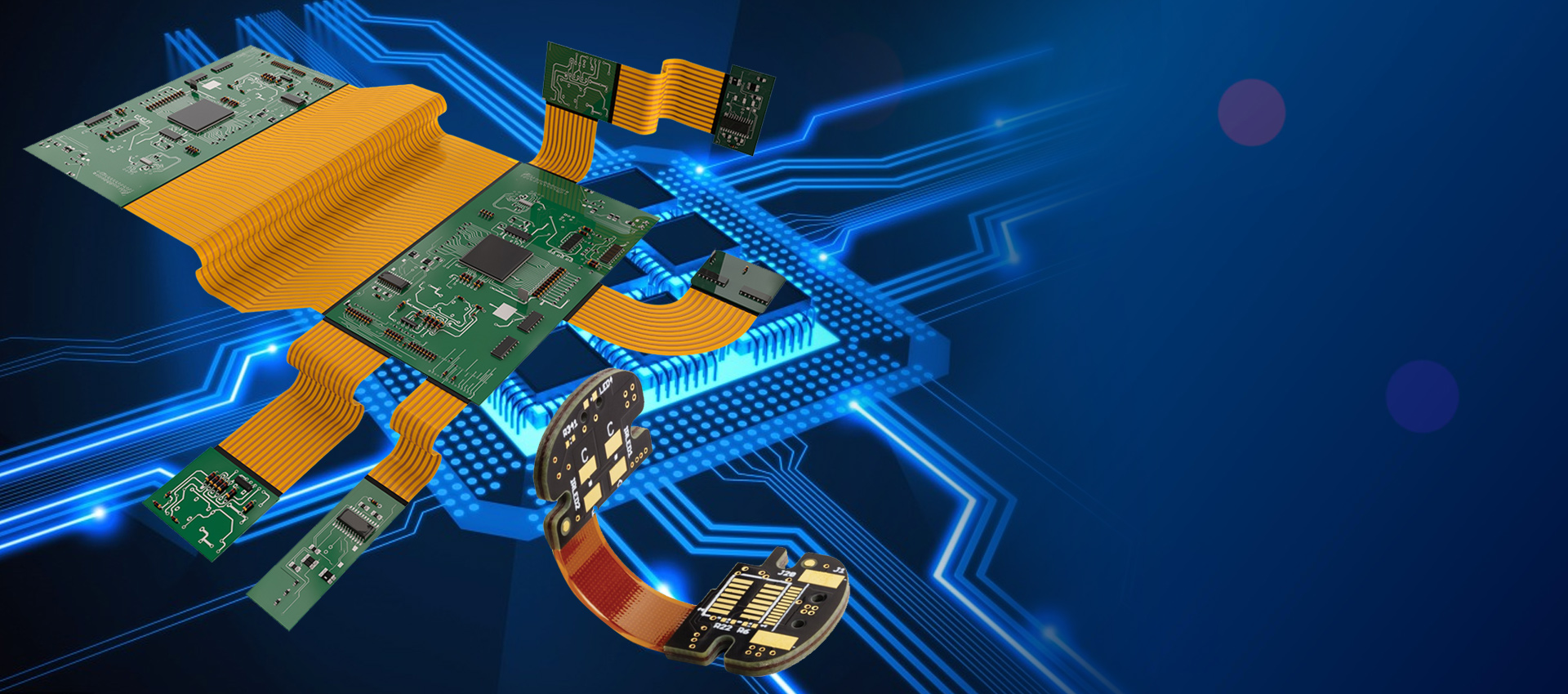
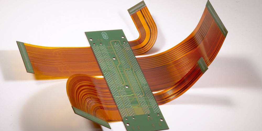
Rigid flex PCBs incorporate both rigid board sections (usually FR-4) and flexible polyimide sections which are joined together into one circuit board. This allows rigid support and stability combined with dynamic flexing ability in one assembly. The rigid and flex materials are laminated together using bonding films. Components can be mounted onto either the rigid or flex sections.
Properties Comparison
Due to the different constructions, flex PCBs and rigid flex PCBs have some varying properties:
| Property | Flex PCB | Rigid Flex PCB |
|---|---|---|
| Rigidity | Very low, flexible only | Rigid in some sections, flexible in others |
| Thickness | Thin, usually around 0.3 – 1 mm | Varies – rigid sections are thicker ~1-2 mm |
| Copper Weight | Very light, usually 1/2 oz | Heavier – 1 or 2 oz copper in rigid sections |
| Layers | Typically 1 or 2 layer | Can support 4 – 12+ layers |
| Minimum Bend Radius | Tight bends down to 2-3 mm | Around 10 mm bend radius in flex areas |
| High Frequency | Often used for high frequency applications | Can allow high frequency transmission in rigid sections |
| Reliability | Prone to wear and tear over time | Very durable construction |
| Repairability | Difficult to repair once damaged | Easier to repair rigid sections |
| Thermal Performance | Prone to overheating | Rigid sections allow heat sinking and cooling |
In summary, rigid flex PCB offers a balance of stability and flexibility whereas pure flex PCBs focus solely on high flexibility in thin circuits.
Design Considerations
Both flex PCB and rigid flex PCB designs require careful layout for functionality and reliability. Here are some of the key differences in design approach:
Flex PCB Design
- Must allow for dynamic flexing, bending, and twisting movements
- Traces routed along controlled bend axes
- Generous bend radii to avoid trace cracking
- Strain relief shapes in traces crossing bend areas
- Minimal components since flex PCB cannot support much weight
- Consider specific applications like dynamic cabling or wearables
Rigid Flex Design
- Determine board sections requiring rigid support vs. flex
- Minimize component bridging across rigid-flex junction
- Provide smooth transitions between rigid and flex areas
- Strain relief for traces between rigid and flex
- Manage differences in thickness between sections
- Ensure stable assembly and integration of components
- Account for three-dimensional folding or staking
Rigid flex PCB design is ultimately more complex than pure flex PCB layout due to the need to integrate the dissimilar substrate materials into one functional circuit board.
Typical Applications
The applications for flex PCB versus rigid flex PCB can be quite different based on their respective properties and constraints:
Flex PCB Applications
- Wearable devices
- Medical sensors
- Dynamic cabling
- Interconnections within medical devices
- Flex-to-board jumpers
- Automotive camera systems
Rigid Flex PCB Applications
- Consumer electronics – laptops, mobile phones
- Aerospace and defense electronics
- Automotive electronics
- Industrial robotics and machinery
- Medical equipment
- Conformal assemblies
Generally rigid flex PCBs are used when a design requires both stability from rigid sections and dynamic flexing in certain areas. Flex PCBs are optimal for simple interconnects needing high flexibility and low profile.
Manufacturing Comparison
Rigid flex PCB fabrication involves some specialized processes beyond normal rigid PCB manufacturing. Here are some key differences:
Rigid Flex PCB Manufacturing
- Lamination of dissimilar materials
- Reinforced rigid-flex interfaces
- Controlled registration and thickness
- Advanced drilling for high layer counts
- Polyimide coverlay for flexible regions
- Flexible solder mask needed
- Specialized testing for flexure durability
Flex PCB Manufacturing
- Simpler lamination of polyimide layers
- No rigid interface considerations
- Standard photolithography processes
- Flexible solder mask or coverlay
- Minimal PCB thickness variations
- Focus on high-volume roll-to-roll processing
Due to the increased complexity, rigid flex PCBs typically have higher costs than pure flexible circuits. However, rigid flex PCBs provide added value through enhanced reliability, design flexibility and integration of both rigid and flex properties.
Frequently Asked Questions
Can components be assembled on both rigid and flex sections?
Yes, components can be surface mounted onto both rigid and flexible sections of a rigid flex PCB. Through-hole components are easier to mount on the rigid segments while avoiding the flexing regions.
What are some examples of dynamic flexing in rigid flex boards?
Common dynamic flexing examples include folding into a curved enclosure, twisting hinges as in laptops, dynamic cabling, and flexing to accommodate movement or vibration.
What are some considerations for traces crossing between rigid and flex?
Use tear-drop pads, rounded corners, and strain relief shapes in traces at the intersections to minimize stress concentrations. Avoid sharp 90 degree angles.
What types of materials can be used?
FR-4, Kapton, and acrylic or epoxy bonding films are most common. More exotic materials like LCP flex can also be used. Copper foils from 0.5 oz to 3 oz support various trace densities.
What are the limitations of rigid flex PCBs?
High cost and design complexity are drawbacks. The minimum bend radius is larger than pure flex PCBs. High temperature processing can be challenging during fabrication.
Conclusion
Rigid flex PCBs occupy a unique technology niche combining the benefits of both rigid boards and flexible circuits into an integrated design. Compared to pure flex PCBs, rigid flex boards offer enhanced structural stability, component mounting, and reliability along with three-dimensional flexibility for compact electronics products requiring dynamic movement. With careful design and fabrication expertise, rigid flex PCBs enable innovative form factors and capabilities beyond traditional rigid boards. The demand for ever more powerful and smaller electronics will ensure rigid flex PCBs continue seeing increased adoption in cutting-edge devices and mission-critical applications.